Tire changer

A technology of tire changer and disassembly mechanism, which is applied in tire installation, tire parts, transportation and packaging, etc., can solve the problems of inability to realize on-board and large volume.

Active Publication Date: 2016-12-07
YINGKOU LIAONAN DEVI MACHINERY EQUIP
View PDF11 Cites 5 Cited by
  • Summary
  • Abstract
  • Description
  • Claims
  • Application Information

AI Technical Summary

Problems solved by technology

However, the existing equipment is

Method used


Image

  • Tire changer

Examples


Embodiment Construction

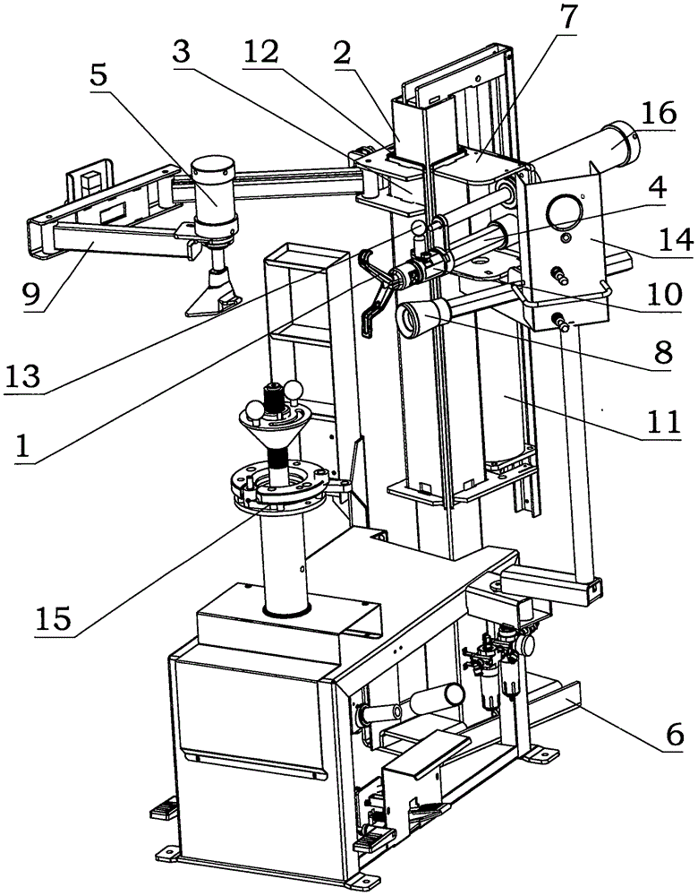
[0007] Below in conjunction with accompanying drawing, the present invention will be further described;

[0008] The body is composed of an operating platform and a disassembly mechanism. On the operating platform, there is a wheel hub fixed disk 15. There is a button switch 14 on one side of the operating platform. There is a square tube slideway foot fixing groove 6 at the bottom of the outer side of the operating platform, and a square tube slideway 2 is provided on the square tube slideway foot fixing groove. One side tube sliding sleeve 3 is set outside the square tube slideway. There is a fixed mount 7 on the top of the square tube sliding sleeve, and on the fixed mount, the tire pressure booster arm 9 has a tire pressure cylinder 5 at the front end of the tire pressure booster arm. A slide block 12 is inlaid between the square tube sliding sleeve and the square tube slideway. The hook head walking cylinder 16 is housed on the top of the fixed mount, and the hook hea...


PUM


Abstract

The invention discloses a tire changer which is simple in structure, small in size and high in automation degree. A body is composed of an operating platform and a mounting and dismounting mechanism. A square tube slide is arranged on a square tube slide foot stand fixing groove. The square tube slide is externally sleeved with a square tube slide bushing. A tire pressing boosting arm is arranged on the left side of a fixing rack, and a mounting and dismounting mechanism lifting cylinder is arranged on the fixing rack at the bottom of the square tube slide bushing. In operation, the square tube slide bushing moves up and down under the action of driving of the mounting and dismounting mechanism lifting cylinder, a tire thread opening is pressed away or pressed into a hub through a tire pressing wheel and a hook head, and then a hub fixing disc is rotated to dismount or mount the tire. In case of special tires or steel wire tires, the boosting arm is needed for collaborative operation. The tire changer is compact in body, low in center of gravity, stable in installation, and high in automation degree as the mounting and dismounting mechanism and a boosting mechanism are integrated. A crowbar is not required to cooperate in mounting and dismounting, and the body can be directly loaded in a tool car and carried to sites of accidents for operation. Practical problems of existing equipment are solved.

Description

technical field [0001] The invention discloses a tire changer, specifically a tire changer with simple structure, small volume and high degree of automation. Background technique [0002] At present, there are roughly three types of tire changers used in actual production; one is the swing arm type, the other is the backward push-pull type, and the hydraulic type. These three models all have uprights installed on the body platform, with swing arms on the uprights. There is a lifting slide bar on the swing arm, and a dismounting head is provided under the slide bar. These three models all have low degree of automation, high manufacturing cost, large body, high center of gravity of the disassembly mechanism on the column, long-term operation makes the joint unstable, complex structure, many operating links and high labor intensity. question. It is necessary to use a crowbar to cooperate in the tire disassembly operation, and it is necessary to temporarily install a booster ...

Claims


Application Information

Patent Timeline
IPC IPC(8): B60C25/138
CPCB60C25/138B60C25/059
Inventor 姜桂林
Owner YINGKOU LIAONAN DEVI MACHINERY EQUIP
Why Eureka
Try Eureka