A center stay lock and an electric vehicle
A technology of movable pins and locking parts, which is applied in the field of electric vehicles, can solve problems such as unstable control of electromagnets, reduced service life, and damage to electromagnets, and achieve the effects of preventing excessive rotation, long service life, and preventing jamming
- Summary
- Abstract
- Description
- Claims
- Application Information
AI Technical Summary
Problems solved by technology
Method used
Image
Examples
Embodiment 1
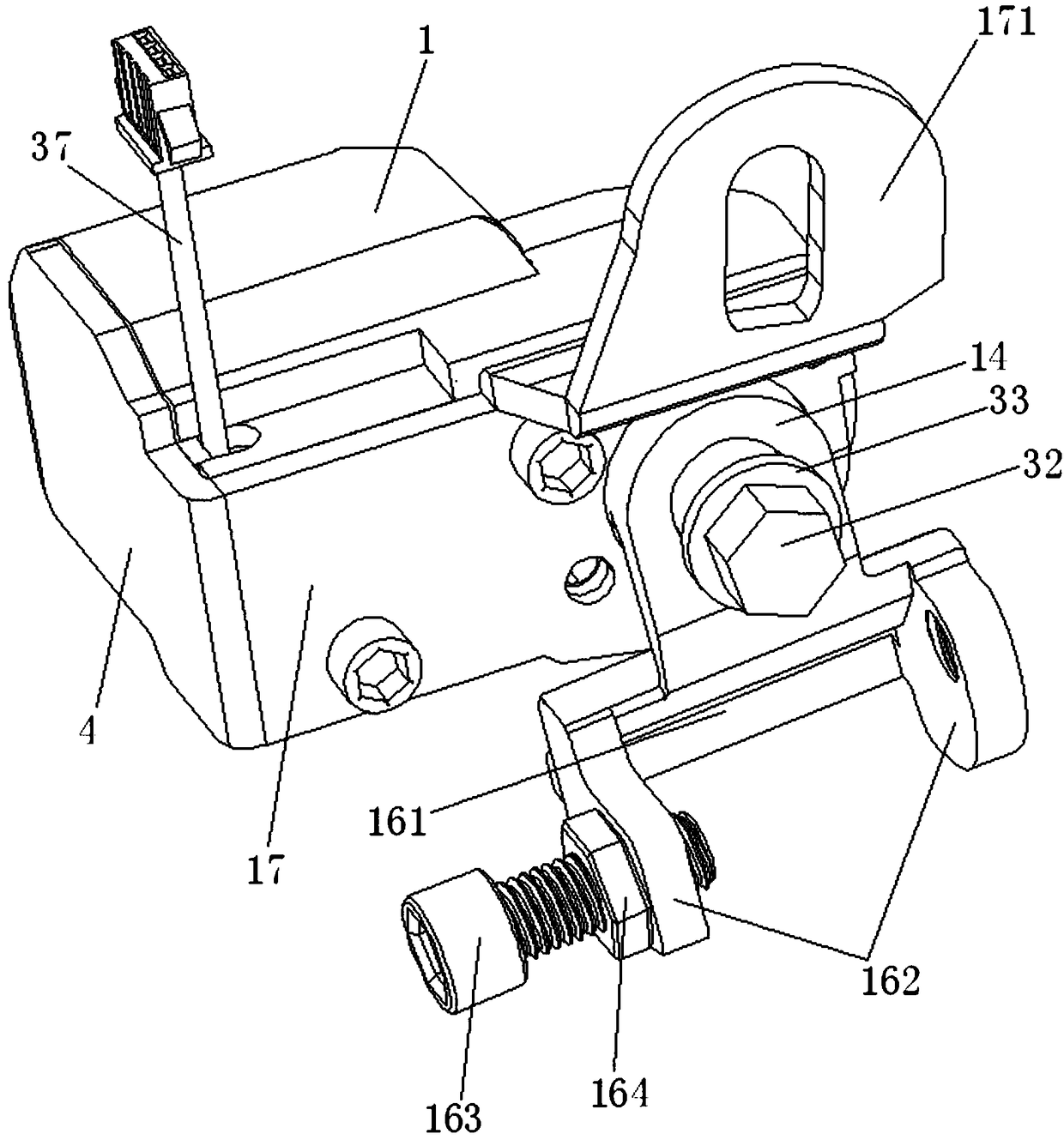
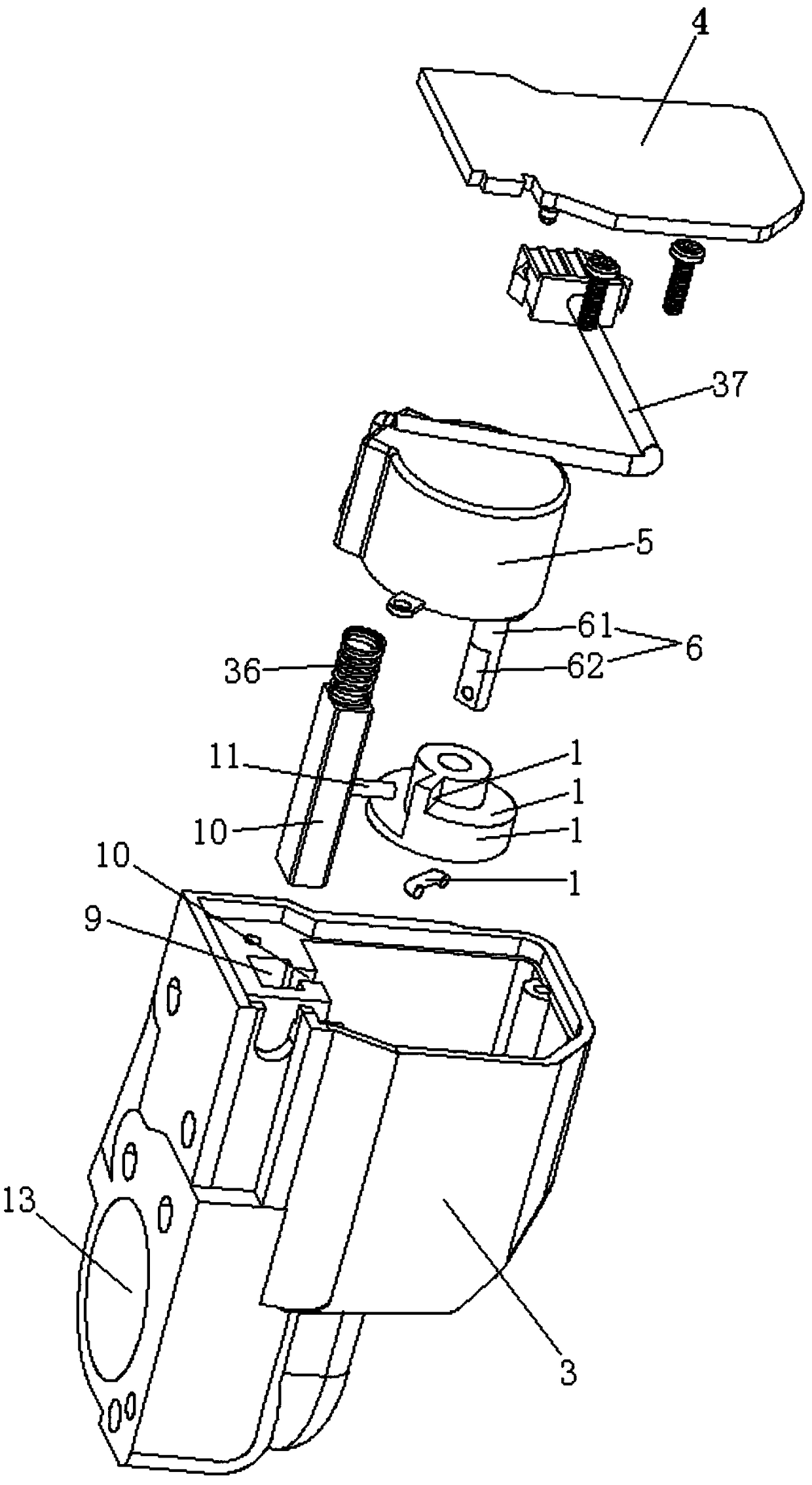
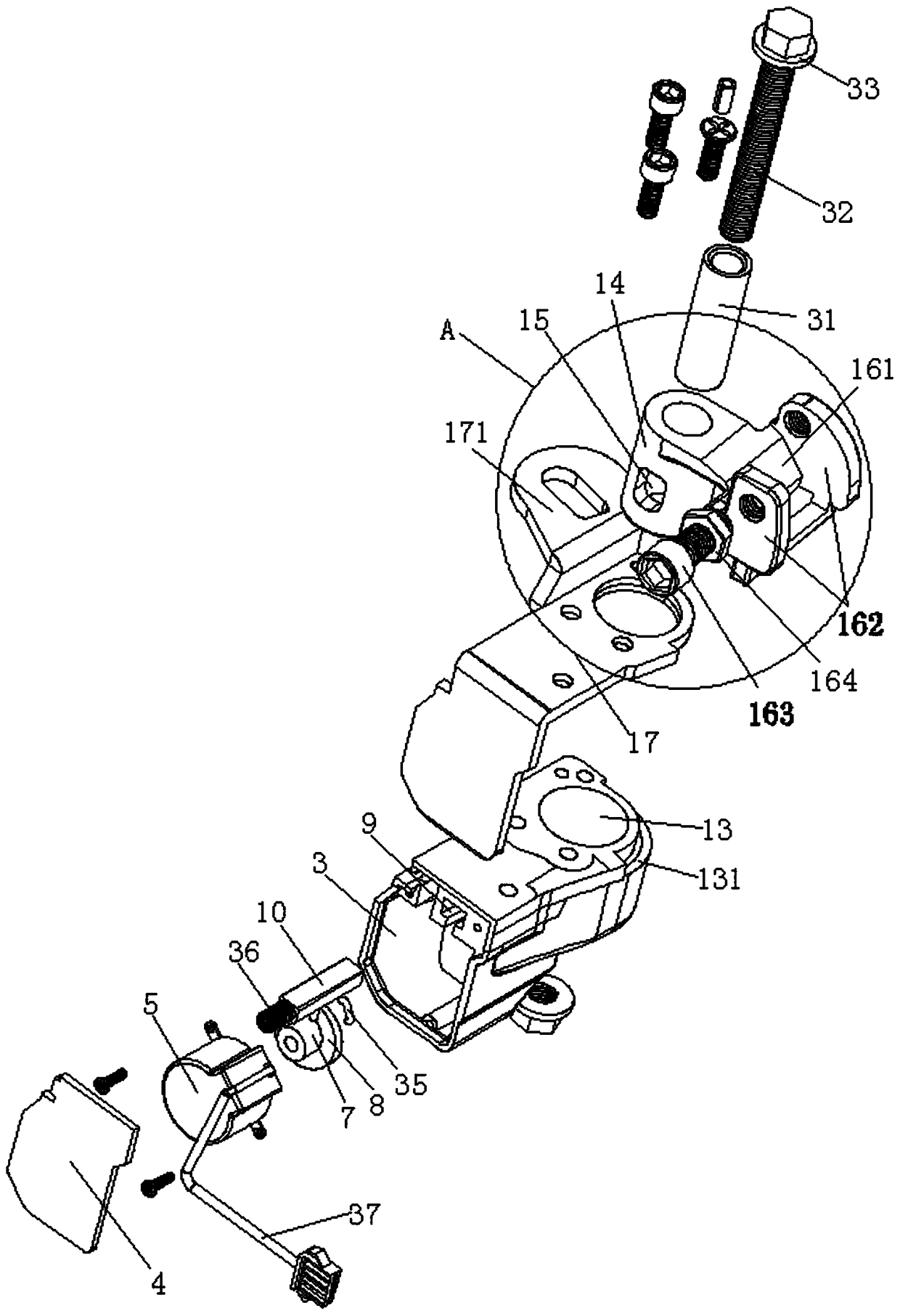
[0059] A middle stay lock, comprising a middle stay lock assembly 1 and a middle stay fixing bolt 2, the middle stay lock assembly 1 includes a middle stay lock housing 3, and the rear end cover 4 of the middle stay lock housing 3 is convenient for installation , set as a detachable connection structure, a motor 5 is fixed in the middle support lock housing 3 by screws, the output shaft 6 of the motor 5 is fixedly connected with a telescopic wheel 7, and a driving slope 8 is formed on the telescopic wheel 7, and the There is also a chute 9 formed in the middle support lock housing 3 and the chute 9 is arranged on the radial side of the motor output shaft 6. A movable pin 10 is slidably arranged in the chute 9, and the middle part of the movable pin extends toward the direction of the motor. The drive rod 11, the drive rod 11 is against the drive slope 7, and the side corresponding to the drive rod 11 of the chute 9 is provided with a slot 12 for the drive rod 11 to slide;
[0...
Embodiment 2
[0085] The structure of this embodiment is basically the same as that of Embodiment 1, the difference is that: the reset device includes a return spring, one end of the return spring abuts against the middle bracket lock housing, a step is formed in the middle of the movable pin, and the return spring The other end of the movable pin abuts against the step of the movable pin, the return spring is in a contracted state, and the return spring drives the front end of the movable pin to leave the bayonet of the locking part, and the driving slope is arranged facing the locking cavity.
Embodiment 3
[0087] The structure of this embodiment is basically the same as that of Embodiment 1, except that the reset device is as follows: the driving slope 8 is set in the middle of the telescopic wheel 7, and the middle of the telescopic wheel 7 is also provided with a reset slope 82 corresponding to the driving slope 8 , the drive slope 8 and the reset slope 82 form a guide rail 83, the drive rod 11 is arranged in the guide rail 83, the motor rotates forward or reversely to drive the telescopic wheel to rotate forward or reversely, and the telescopic wheel rotates forwardly or reversely to drive and fix the drive rod The connected movable pin performs telescopic movement, and this structure can realize the reset of the movable pin through the reverse rotation of the motor, thereby avoiding the occurrence of the stuck movable pin.
[0088] The present invention has the characteristics of simple structure, convenient use, long service life, stable driving, no jamming phenomenon, and i...
PUM
 Abstract
Description
Claims
Application Information
 - R&D
- Intellectual Property
- Life Sciences
- Materials
- Tech Scout
- Unparalleled Data Quality
- Higher Quality Content
- 60% Fewer Hallucinations
Browse by: Latest US Patents, China's latest patents, Technical Efficacy Thesaurus, Application Domain, Technology Topic, Popular Technical Reports.
© 2025 PatSnap. All rights reserved.Legal|Privacy policy|Modern Slavery Act Transparency Statement|Sitemap|About US| Contact US: help@patsnap.com


