
Retractable Rudder Wing Mechanism for Marine Vehicle

A technology of aircraft and rudder wing, which is applied in the field of retractable rudder wing mechanism of marine aircraft, can solve problems such as easy damage to the shaft system, difficulty in recovering the deformation of the rudder shaft, and unguaranteed safety, so as to ensure safety, reliability, high Practical value, the effect of high practical value

Active Publication Date: 2017-11-21
HARBIN ENG UNIV
View PDF4 Cites 0 Cited by
  • Summary
  • Abstract
  • Description
  • Claims
  • Application Information

AI Technical Summary

Problems solved by technology

In order to protect the rudder wing from damage, people are often arranged to hold the hull of the aircraft to control its direction. The weight of the aircraft ranges from a few hundred kilograms to several tons. The safety of personnel cannot be guaranteed, especially during sea trials. The knocking phenomenon caused by the shaking of the lifting device under the influence of wind and waves is especially common
[0005] Secondly, during the transportation of the aircraft, the shafting is easily damaged
The rudder wings of most aircrafts will be detachable, and the rudder blades will be removed and transported separately during packing and transportation, which will protect the rudder wings, but the rudder shaft will be directly exposed to the outside, and the bending of the rudder shaft will Affect the overall performance of the rudder system, and the deformation of the rudder shaft is difficult to recover
These will affect the aircraft

Method used


Image

  • Retractable Rudder Wing Mechanism for Marine Vehicle
  • Retractable Rudder Wing Mechanism for Marine Vehicle
  • Retractable Rudder Wing Mechanism for Marine Vehicle

Examples


Embodiment Construction

[0018] The present invention will be further described in detail below in conjunction with the accompanying drawings and specific embodiments.

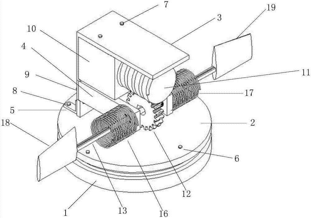
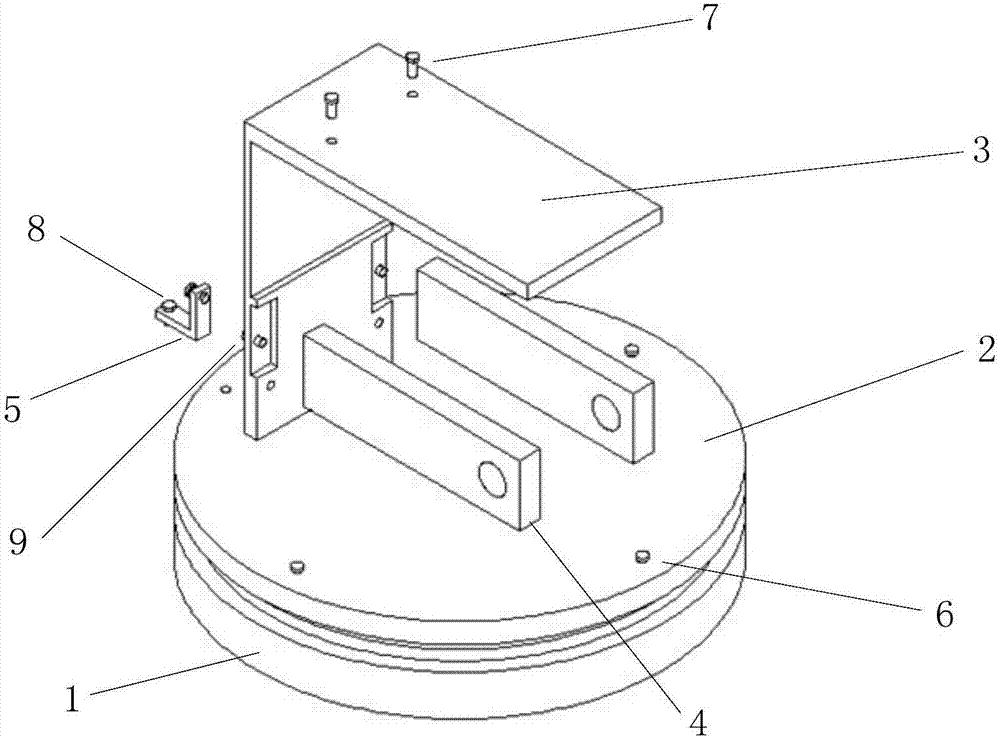
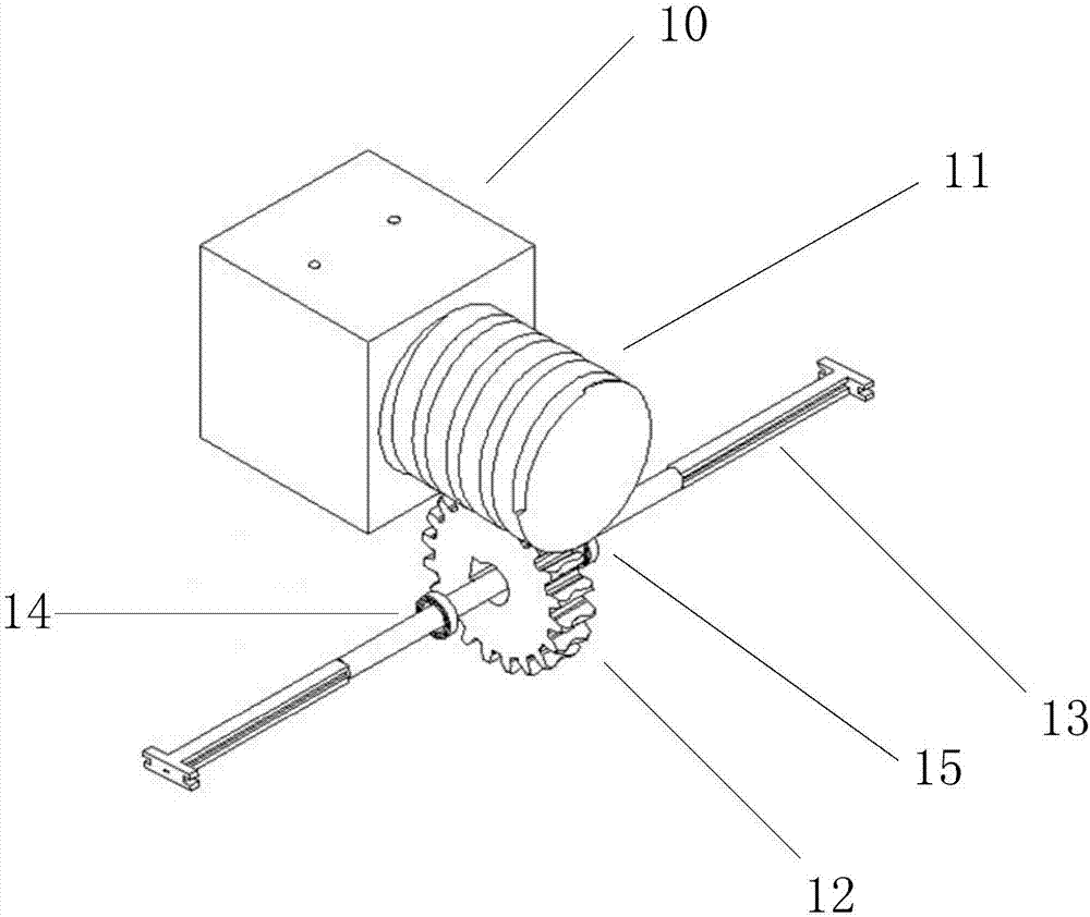
[0019] combine Figure 1 to Figure 6 , the present invention includes a support structure, a shafting structure, a rudder wing system and a control circuit. The rudder wing moves in translation along the rudder axis, and the control circuit is integrated in the cabin to control the electromagnet and coil to be powered on. The middle part of the rudder shaft is cylindrical, and the outwards are I-shaped in turn, and the two ends are widened I-shaped, and there is a wire channel inside the rudder shaft. The solenoid is fixed on the baffle, the terminals at both ends are connected to the cabin, and the control circuit controls power on. The rudder wing is plugged on the rudder shaft and can slide on the rudder shaft. There are baffles on the top and bottom of the slot inside the rudder wing, and coils are integrated around the slot. Th...


PUM


Abstract

The invention provides a retractable rudder wing structure of a marine aircraft. The retractable rudder wing structure comprises a cabin and a cabin cover arranged on the cabin. A support is mounted on the cabin cover. A motor is mounted on the support. Two baffles are symmetrically mounted on the parts, under the motor, of the support. A worm is mounted on an output shaft of the motor and engaged with a worm wheel. The worm wheel is mounted on a rudder shaft. The two ends of the rudder shaft penetrate through the two baffles correspondingly. A solenoid is mounted on the outer side face of each baffle. The two ends of the rudder shaft are inserted into two hollow rudder wings correspondingly. A coil is arranged in each rudder wing. The rudder shaft is hollow, and a positive wire and a negative wire are integrated at each end in the rudder shaft. The two ends of each coil are connected with the corresponding positive wire and the corresponding negative wire. The two coils and the two solenoids are all connected with a control circuit arranged in the cabin. The retractable rudder wing structure is simple in structure, capable of saving energy, high in practical value and capable of achieving the rudder wing recovery task of the underwater aircraft, and the safety and reliability of the underwater aircraft are ensured.

Description

technical field [0001] The invention relates to a control surface mechanism of a marine vehicle, in particular to a retractable rudder wing mechanism of a marine vehicle. Background technique [0002] Marine vehicles originated from the exploration of the ocean by humans. Since the beginning of the new century, with the deepening of human research on the ocean, marine vehicles have achieved vigorous development, and various marine detection equipment have emerged, including HOV, ROV, UUV, AUV, etc. These devices have played an indelible role in human exploration of the ocean. The differences in the degree of intelligent control and manipulation methods are the basis for classification. Apart from these differences, in their movements, more or less The rudder will be used to steer and stabilize the flow. Among them, the autonomous underwater robot, that is, AUV, mostly uses paddle-rudder joint control, which has many advantages such as simple structure and easy control, and ...

Claims


Application Information

Patent Timeline
Patent Type & Authority Patents(China)
IPC IPC(8): B63H25/38
CPCB63G2008/002B63H25/382B63H2025/384
Inventor 李晔郭宏达龚昊王汝鹏安力乔岳坤曹建姜言清马腾付悦文
Owner HARBIN ENG UNIV
Learn More