Tape dispenser

A technology of dispensers and components, applied in the field of belt dispensers

Active Publication Date: 2016-12-07
KOKUYO CO LTD
View PDF6 Cites 0 Cited by
  • Summary
  • Abstract
  • Description
  • Claims
  • Application Information

AI Technical Summary

Problems solved by technology

[0003] However, on the other hand, there is also the difficulty of pinching the top end of the tape to pull out the tape when the top end of the tape protrudes sufficiently from the tape dispenser.

Method used


Image

  • Tape dispenser
  • Tape dispenser
  • Tape dispenser

Examples


Embodiment Construction

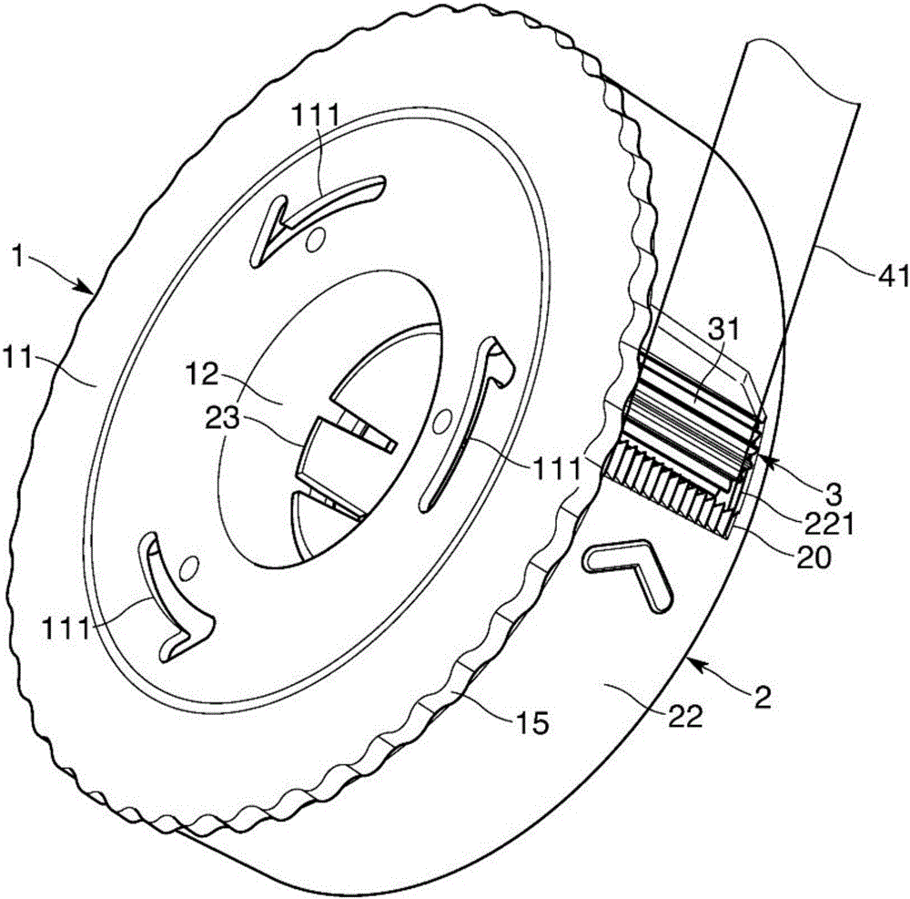
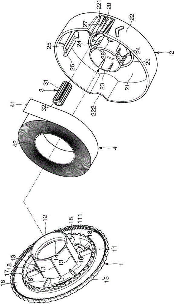
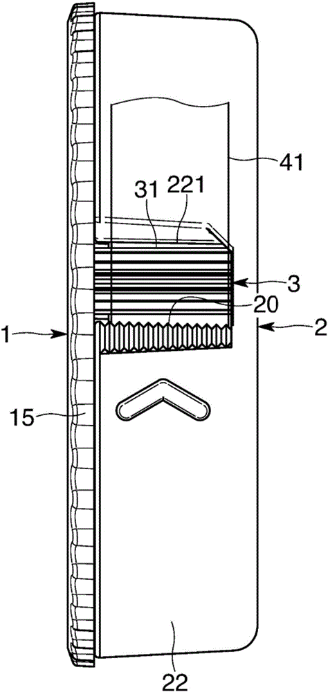
[0035] One embodiment of the present invention will be described with reference to the drawings. Such as Figure 1 to Figure 6 As shown, the tape dispenser of the present embodiment is provided with: accommodating and holding a first part 1 and a second part 2 of a reel 4 wound with a tape 41; a tape guide 3 for feeding out from the tape dispenser; and a cutting blade 20 for cutting the tape 41 sent out by the operation of the tape guide 3 . In addition, in Figure 5 as well as Image 6 In the sectional view of , the belt 41 and the reel 4 are drawn by dotted lines.

[0036] Such as figure 2 , Figure 5 as well as Image 6 As shown, the cover 1 as the first member is, for example, an integrally molded product made of hard resin, and has a general shape in which a support shaft 12 protrudes inward from a center portion on the inner surface of a substantially disk-shaped side plate 11 . The outer diameter of the side plate 11 is larger than the outer diameter of the reel...


PUM


Abstract

A tape dispenser which can pull out a tape simply at the time of necessity is provided. The tape dispenser consists of a first part which supports a reel with a tape; the second part that can rotate relatively to the first part and the reel; and a tape guide part which contacts with the uppermost layer of the reel to rotate along with the first and second parts, thereby enabling the tape at the uppermost layer to carry out the movement for discharge relative to the second part.

Description

technical field [0001] The present invention relates to a tape dispenser that is capable of pulling and cutting the required amount of tape from a spool when needed. Background technique [0002] There is known a tape dispenser that accommodates and holds a tape such as an adhesive tape, and can pull out the tape and cut it with a cutting blade when necessary (for example, refer to the following patent documents). Such a tape dispenser has the advantage of being able to cover the spool on which the tape is wound to prevent contamination when not in use. [0003] However, on the other hand, there is a difficulty in that it is difficult to pinch the leading end of the tape to pull out the tape when the leading end of the tape protrudes sufficiently from the tape dispenser. [0004] prior art literature [0005] patent documents [0006] Patent Document 1: Japanese Patent Application Laid-Open No. 10-120282 Contents of the invention [0007] The problem to be solved by th...

Claims


Application Information

Patent Timeline
Patent Type & Authority Applications(China)
IPC IPC(8): B65H35/06
CPCB65H35/06B65H2701/19
Inventor 山本尚甲斐启二
Owner KOKUYO CO LTD
Why Eureka
Try Eureka