Novel side beam structure of elevator counterweight framework

A technology for side beams and elevators, which is applied in the field of side beam structures of new elevator counterweight frames, can solve the problems of long processing length, difficult processing, and difficult installation of counterweight blocks, and achieve the effects of reducing difficulty, increasing speed, and facilitating loading.

Inactive Publication Date: 2016-12-07
TIANJIN ELEVATOR ELEVATOR PARTS
View PDF9 Cites 2 Cited by
  • Summary
  • Abstract
  • Description
  • Claims
  • Application Information

AI Technical Summary

Problems solved by technology

[0002] In the existing elevator counterweight frame, the structure of the side beam is produced by a flat plate through punching, bending and other processes. For some relatively long counterweight frame side beams, especially the high-speed ladder type counterweight For frame side beams, the required bending machine can meet the processing length is very large, the bending machine used to manufacture general ladder-type counterweight frame side beams cannot meet the processing requirements of relatively long counterweight frame side beams such as high-speed ladder type, and , There are also many difficulties in the processing of such super-long counterweight frame side beams, and the machining accuracy, especially the machining accuracy of the middle part of the side beams, is difficult to meet the requirements of the drawings. The counterweight frame side beam struct

Method used


Image

  • Novel side beam structure of elevator counterweight framework
  • Novel side beam structure of elevator counterweight framework

Examples


Embodiment Construction

[0014] The specific implementation, structure, features and effects provided by the present invention will be described in detail below in conjunction with the accompanying drawings and preferred embodiments.

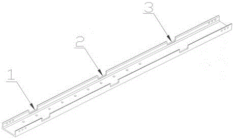
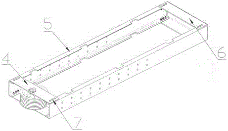
[0015] A new elevator counterweight frame side beam structure, comprising: side beam 5, rope sheave assembly combination 4, lower beam 6, said side beam 5 is an integrally formed channel steel profile, two side beams are arranged opposite to each other, two side beams A lower beam 6 is provided between the bottoms of the beams, and a rope pulley assembly 4 is provided between the tops of the two side beams. The side beams 5, the lower beam 6 and the rope pulley assembly 4 are connected by fasteners 7. Three counterweight mounting holes, namely upper counterweight mounting hole 1, middle counterweight mounting hole 2, and lower counterweight mounting hole 3, are respectively distributed on the side beam 5.

[0016] The upper counterweight installation hole 1 , the middle...


PUM


Abstract

The invention discloses a novel side beam structure of an elevator counterweight framework. The novel side beam structure comprises side beams, a rope wheel assembly and a lower beam; the side beam is an integrally formed channel steel section bar; the two side beams are oppositely arranged; the lower beam is arranged between bottoms of the two side beams; the rope wheel assembly is arranged between tops of the two side beams; the side beams, the lower beam and the rope wheel assembly are connected though a fastener; and an upper counterweight block mounting hole, a middle counterweight block mounting hole and a lower counterweight block mounting hole are separately distributed in each of the two side beams. The novel side beam structure has the advantages and the beneficial effects that: the side beams do not need to bend, processing of side beams of the counterweight framework can be completed through processes such as punching, and the problems that processing difficulty is great and processing precision cannot meet requirements of a drawing in producing and processing for ultra-long side beams of the counterweight framework are solved; and upper, middle and lower counterweight block mounting holes are separately distributed in the side beams, so that the condition that one end of a counterweight block is blocked on the side beams of the counterweight framework and cannot be horizontally mounted on the bottom of the counterweight framework is avoided, and the counterweight blocks are conveniently filled, and therefore, elevator mounting speed is improved.

Description

technical field [0001] The invention belongs to the field of elevator accessories and relates to a novel elevator counterweight frame side beam structure. Background technique [0002] In the existing elevator counterweight frame, the structure of the side beam is produced by a flat plate through punching, bending and other processes. For some relatively long counterweight frame side beams, especially the high-speed ladder type counterweight For frame side beams, the required bending machine can meet the processing length is very large, the bending machine used to manufacture general ladder-type counterweight frame side beams cannot meet the processing requirements of relatively long counterweight frame side beams such as high-speed ladder type, and , There are also many difficulties in the processing of such super-long counterweight frame side beams, and the machining accuracy, especially the machining accuracy of the middle part of the side beams, is difficult to meet the ...

Claims


Application Information

Patent Timeline
IPC IPC(8): B66B11/04B66B17/12
CPCB66B11/04B66B17/12
Inventor 王亮
Owner TIANJIN ELEVATOR ELEVATOR PARTS
Why Eureka
Try Eureka