A drying device for windows
A technology for drying devices and windows, which is applied to washing devices, other drying devices, special equipment for doors/windows, etc., to achieve the effects of reducing labor intensity, realizing remote control, and ensuring the cost of use
- Summary
- Abstract
- Description
- Claims
- Application Information
AI Technical Summary
Problems solved by technology
Method used
Image
Examples
Embodiment 1
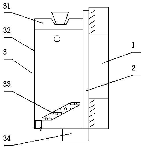
[0037] like figure 1 As shown, the drying device for windows of the present invention includes a drying rack 32, a drying rod, a top plate 31, and a flow guide device 33; 33 is located directly below the drying rod, and the top plate 31 is located on the top of the drying rack 32; the drying device 3 is installed on the outside of the window 1.
[0038]A pit is set on the upper surface of the top plate 31, and the pit is used to place potted plants. A rubber pad is arranged at the bottom of the pit, and the bottom of the pit is communicated in the sewer pipe through a pipeline. The design can be used for placing potted plants. In addition, it can ensure that the pits will not accumulate water, and the potted plants can be used to beautify the environment and improve living comfort.
[0039] The drying device 3 is installed on the outside of the window 1 through the lifting device 2, and the lifting device 2 can move the top plate 31 to the top or bottom of the window 1. The ...
Embodiment 2
[0044] Based on the drying device 3 of embodiment 1, its intelligent drying system also includes a lifting device 2, a controller, and a power unit 34;
[0045] The lifting device 2 includes a moving slide rail and a static slide rail, the static slide rail is fixed on the outer wall of the window 1, and the moving slide rail is connected to the drying rack 32 and can slide up and down along the static slide rail;
[0046] The deflector 33 includes a plurality of parallel deflectors that cooperate with each other in a stepped shape, and a deflector slot positioned obliquely below the deflectors; the deflectors are connected to the drying rack 32 through the rotating shafts on both sides, and the adjacent The guide plates are connected by guide ropes, and the guide ropes make the guide plates rotate in the same direction around their rotation axes; a reflective layer is arranged on the upper surface of the guide plates, and the reflective layer is set in a concave shape;
[004...
Embodiment 3
[0053] Based on the drying device of embodiment 1 or the intelligent drying system of embodiment 2, its intelligent drying method is:
[0054] Step 1: Control the drying rack 32 to rise to the window 1 through the controller, hang the clothes and trousers on the drying rod, and lower the drying rack 32 to the lower part of the window 1;
[0055] Step 2: The water on the clothes flows down to the deflector, then flows along the deflector and flows into the sewer pipe through the diversion groove;
[0056] Step 3: the controller controls the screen to be lowered at night to cover the drying rack 32, and the screen is put away during the day to open the drying rack 32;
[0057] Step 4: At 8-10 o'clock, the controller controls the inclination angle of the deflector to the horizontal direction to be 30-45°; at 10-12 o'clock, the controller controls the inclination angle of the deflector to be 15-29°; 12- At 14 o'clock, the controller controls the inclination angle of the deflector...
PUM
 Abstract
Description
Claims
Application Information
 - R&D
- Intellectual Property
- Life Sciences
- Materials
- Tech Scout
- Unparalleled Data Quality
- Higher Quality Content
- 60% Fewer Hallucinations
Browse by: Latest US Patents, China's latest patents, Technical Efficacy Thesaurus, Application Domain, Technology Topic, Popular Technical Reports.
© 2025 PatSnap. All rights reserved.Legal|Privacy policy|Modern Slavery Act Transparency Statement|Sitemap|About US| Contact US: help@patsnap.com

