Cylinder with locking device

A technology of locking device and cylinder, which is applied in the direction of fluid pressure actuating device, etc., can solve the problem of poor pressure holding effect and achieve the effect of improving the pressure holding effect

Inactive Publication Date: 2016-12-07
广州白云液压机械厂有限公司
View PDF2 Cites 4 Cited by
  • Summary
  • Abstract
  • Description
  • Claims
  • Application Information

AI Technical Summary

Problems solved by technology

[0005] The technical problem mainly solved by the present invention is to provide a cylinder with a locking device, which solves the technical problem that the above-mentioned cylinder control and pressure maintaining effect are not good

Method used


Image

  • Cylinder with locking device
  • Cylinder with locking device
  • Cylinder with locking device

Examples


Embodiment Construction

[0022] The present invention will be described in detail below in conjunction with the accompanying drawings and embodiments.

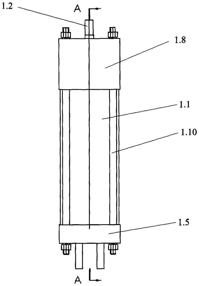
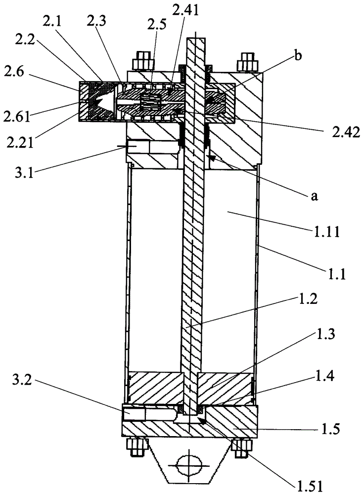
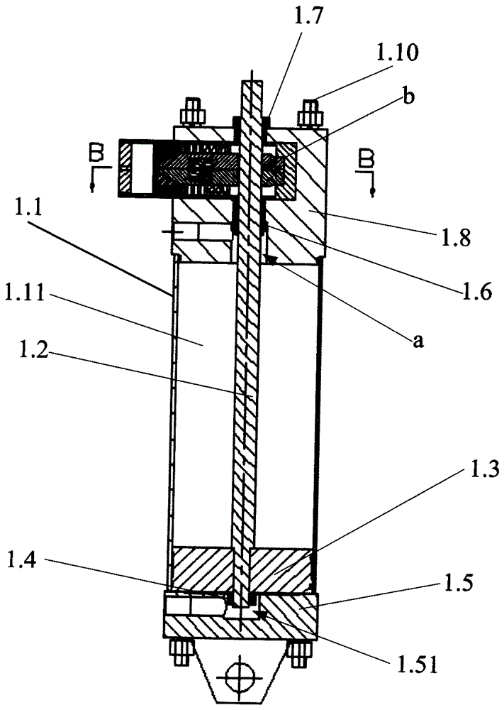
[0023] refer to figure 1 , figure 2 , image 3 and Figure 4 as shown, figure 1 It is a schematic diagram of a three-dimensional structure of a cylinder with a locking device in the present invention; figure 2 Yes figure 1 Schematic diagram of the cutaway structure of the A-A line where the middle cylinder is in a locked state; image 3 Yes figure 1 Schematic diagram of the cutaway structure of the A-A line where the middle cylinder is in the unlocked state; Figure 4 Yes image 3 Schematic diagram of the cross-sectional structure of the B-B line of the middle cylinder. A cylinder with a locking device disclosed in the present invention comprises a cylinder body, a piston rod 1.2 and a locking device.

[0024] The cylinder body includes a cylinder barrel 1.1, a front end cover 1.8 and a rear end cover 1.5 arranged at both ends of the cylin...


PUM


Abstract

The invention discloses a cylinder with a locking device. The cylinder with the locking device comprises a cylinder body, a piston rod and the locking device, wherein the cylinder body is composed of a cylinder barrel, a front end cover and a back end cover; the front end cover and the back end cover are arranged at the two ends of the cylinder barrel; a first cavity is formed in the cylinder barrel; a first through hole is formed in the front end cover; a first blind hole is formed in the back end cover; the first through hole and the first blind hole communicate with the first cavity separately; the piston rod is movably arranged in the first through hole, the first cavity and the first blind hole; one end, far away from the front end cover, of the piston rod is provided with a piston; the piston is movably arranged in the first cavity; and the locking device is arranged in the front end cover, is connected with the piston rod and is used for controlling the piston rod to be in a locking state or an unlocking state in the cylinder body. According to the cylinder with the locking device, with the mode, the cylinder can be locked by the locking device, so that the cylinder cannot automatically open, and the pressure holding effect of the cylinder is greatly improved.

Description

technical field [0001] The invention relates to the technical field of cylinders, in particular to a cylinder with a locking device. Background technique [0002] During the working process of electrolytic aluminum, there is a grab device, whose function is to grab the anode residue and oxidized fragments in the electrolytic aluminum tank. The first step of the grab is to reach into the electrolytic tank to grab the anode residues and oxidized fragments. In the second step, the grab is closed, and they are put into a special storage place through the rotation of the hydraulic motor of the electrolytic aluminum crane. The anode residues and oxidized fragments picked up by the grab will stick to the grab due to the action of the electrolyte, and the aluminum water remaining in the grab will directly stick to the grab body, forming a layer of aluminum blocks, which will affect the grip if it takes a long time. fighting action. Therefore, it is necessary to shake the slag of t...

Claims


Application Information

Patent Timeline
Patent Type & Authority Applications(China)
IPC IPC(8): F15B15/26
Inventor 李志俊陈志宏李振立陈裕银谢建辉王金城刘安毅刘付金文王苏珊赖志刚沈新超饶泽鹏
Owner 广州白云液压机械厂有限公司
Why Eureka
Try Eureka