A double-indicating device for angular strokes for butterfly valves

A technology of indicating device and angular stroke, applied in valve device, valve operation/release device, valve details, etc., can solve the problem of not being able to know the degree of valve opening and closing from multiple angles, and achieve light weight, compact structure, Easy-to-use effects

Active Publication Date: 2018-08-21
GUANGDONG YONGQUAN VALVE TECH
View PDF8 Cites 0 Cited by
  • Summary
  • Abstract
  • Description
  • Claims
  • Application Information

AI Technical Summary

Problems solved by technology

[0004] The technical problem to be solved by the present invention is to provide a double angular stroke indicator device for butterfly valves, which can make the pointer disc The steering of the butterfly plate is consistent with the steering of the butterfly plate and the pointer disk of the valve driving device, and is fully synchronized with the rotation angle of the butterfly plate and the pointer disk of the valve driving device, and can accurately indicate the opening or closing position of the valve; therefore, it can be a good solution to the existing butterfly valve. The problem that the angular stroke drive device cannot know the degree of valve opening and closing from multiple angles

Method used


Image

  • A double-indicating device for angular strokes for butterfly valves
  • A double-indicating device for angular strokes for butterfly valves
  • A double-indicating device for angular strokes for butterfly valves

Examples


Embodiment Construction

[0032] Below, in conjunction with accompanying drawing and specific embodiment, the present invention is described further:

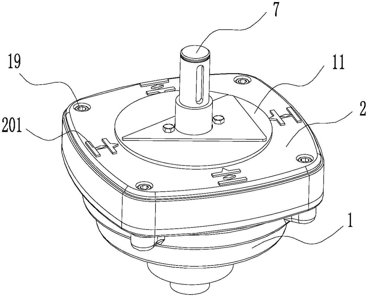
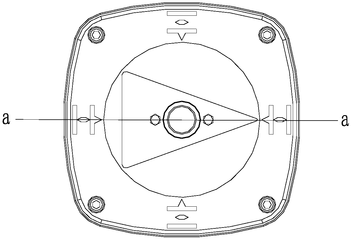
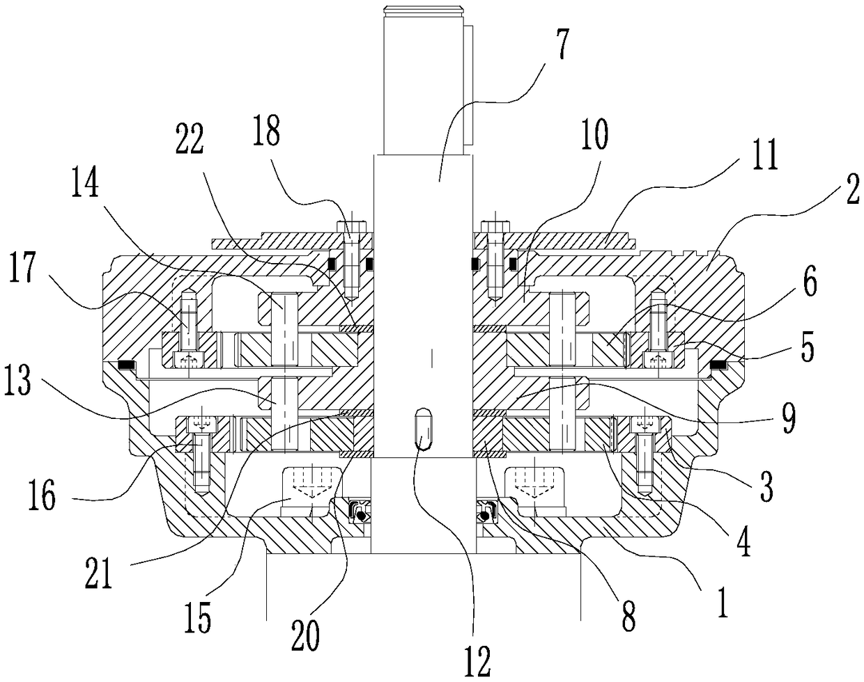
[0033] like Figure 1-6 As shown, a butterfly valve angular travel double indicating device 100 includes a lower gear seat 1, an upper gear seat 2, a first internal gear 3, a first external gear 4, a second internal gear 5, a second external gear 6, an input Shaft 7, eccentric sleeve 8, eccentric frame 9, output frame 10, pointer plate 11;

[0034] The upper gear seat 2 is fixed on the lower gear seat 1 by the fifth screw 19, and forms an accommodating cavity; the input shaft runs through the upper and lower gear seats; the first internal gear and the first external gear , the second internal gear, the second external gear, the eccentric sleeve, the eccentric frame, and the output frame are all arranged in the accommodating cavity; the lower gear seat is fixed on the valve driving device by the first screw 15; the input shaft It is connected with the ...


PUM


Abstract

The invention discloses an angular travel dual-indication device for a butterfly valve. The angular travel dual-indication device for the butterfly valve comprises an upper gear seat, a lower gear seat, a first internal gear, a second internal gear, a first external gear, a second external gear, an input shaft, an eccentric sleeve, an eccentric rack, an output rack and a pointer disc. The upper gear seat is fixed to the lower gear seat. The input shaft is sleeved with the eccentric sleeve and is in transmission connected with the eccentric sleeve. The eccentric sleeve is sleeved with the first external gear. The first external gear is sleeved with the first internal gear, and the first internal gear is engaged with external teeth of the first external gear. The first internal gear is fixed to the lower gear seat. The input shaft is sleeved with the eccentric rack, and the eccentric rack is in transmission connection with the first external gear. The eccentric rack is sleeved with the second external gear. The second external gear is sleeved with the second internal gear, and the second internal gear is engaged with external teeth of the second external gear. The second internal gear is fixed to the upper gear seat. An output shaft is sleeved with the output rack, and the output rack is in transmission connection with the second external gear. The pointer disc is fixedly connected to the output rack. By the adoption of the angular travel dual-indication device for the butterfly valve, the problem that the opening and closing degree of a valve cannot be known from multiple angles through an existing angular travel driving device for a butterfly valve is solved.

Description

technical field [0001] The invention relates to the technical field of valve accessories, and more specifically relates to an angular stroke double indicating device for a butterfly valve. Background technique [0002] The butterfly valve is driven by the valve drive device through the valve shaft to drive the butterfly plate to rotate 90° around the axis of the valve shaft to achieve the purpose of opening and closing or adjustment. At present, most commonly used butterfly valves use a valve drive device composed of worm gear and worm to control the opening and closing of the butterfly. There is only one opening indicator of the butterfly valve, which is usually set at the shaft end of the butterfly valve. The dial is fixed on the worm gear box, and the pointer is fixed on the worm gear. , which requires the operator to stand directly in front of the shaft end of the butterfly valve to observe the opening and closing of the valve. However, some projects require that the bu...

Claims


Application Information

Patent Timeline
Patent Type & Authority Patents(China)
IPC IPC(8): F16K37/00F16K31/53
CPCF16K31/53F16K37/00
Inventor 李茜民熊初庆梁建林陈键明区展剑黄仲荣吴柏敏黎彪黄明亮潘庆祥霍达文何国豪
Owner GUANGDONG YONGQUAN VALVE TECH
Why Eureka
Try Eureka