Condensate water dripping preventing structure at water dripping pipe position of evaporator

A technology for preventing condensed water and evaporators, which is applied in the field of automotive air conditioning, and can solve problems such as passenger inconvenience

Inactive Publication Date: 2016-12-07
ANHUI JIANGHUAI SONGZ AIR CONDITIONING
View PDF5 Cites 3 Cited by
  • Summary
  • Abstract
  • Description
  • Claims
  • Application Information

AI Technical Summary

Problems solved by technology

[0005] The technical problem to be solved by the present invention is to provide an anti-condensed water dripping structure at the drip pipe of the evaporator, so as to solve the problem that in the existing structure, part of the condensed water will be precipitated on the outer surface of the lower shell of the evaporator, and the condensed water will evaporate when it evaporates. The surface of the lower shell of the device flows in different directions, and the accumulation of small amounts will drip into the interior of the cab, causing inconvenience to passengers

Method used


Image

  • Condensate water dripping preventing structure at water dripping pipe position of evaporator
  • Condensate water dripping preventing structure at water dripping pipe position of evaporator
  • Condensate water dripping preventing structure at water dripping pipe position of evaporator

Examples


Embodiment Construction

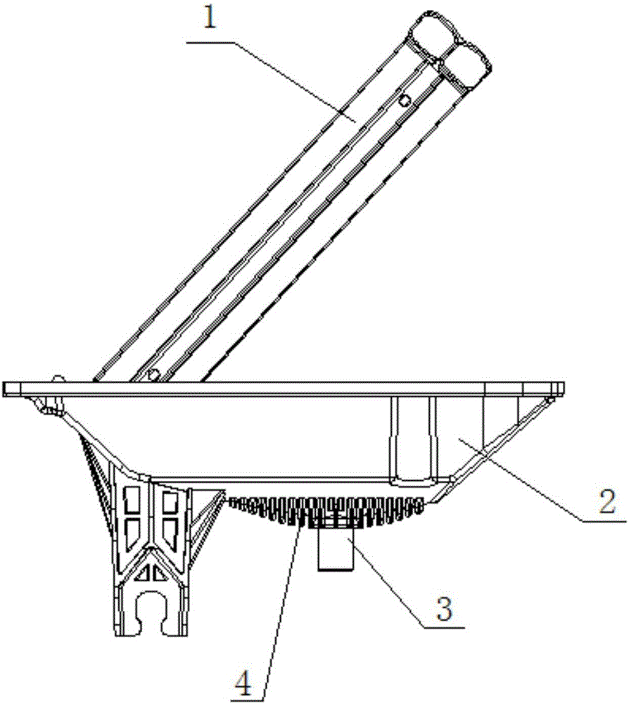
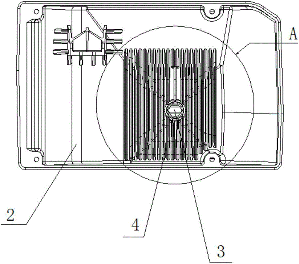
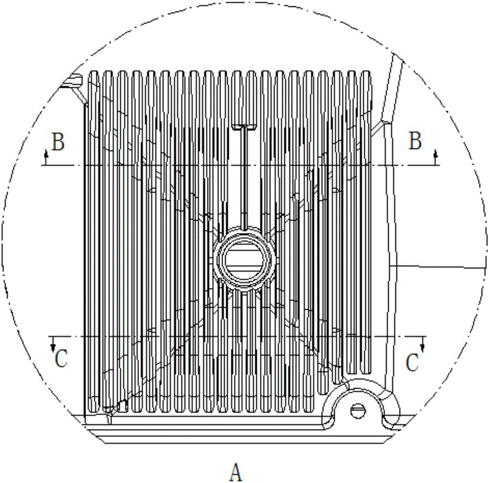
[0019] Such as Figure 1 to Figure 5 As shown, the present invention provides an anti-condensation water dripping structure at the drip pipe of the evaporator, including: an evaporator core 1, an evaporator lower shell 2 arranged outside the evaporator core 1, and an evaporator lower shell 2 The drip pipe 3 connected at the bottom and several ribs 4 arranged on the bottom surface of the lower shell 2 of the evaporator.

[0020] Specifically, several ribs 4 are parallel to each other. By adding the above-mentioned structure at the drip pipe 3, when condensed water precipitates on the surface of the lower shell 2 of the evaporator, the arrangement of the tight ribs 4 limits the flow of condensed water in the evaporator. With the free flow of the lower shell 2, the condensed water can evaporate freely, and will not accumulate and drip into the cab. At the same time, this design can save a waterproof sponge on the inner surface, and save a sponge to be pasted into the lower shell ...


PUM


Abstract

The invention provides a condensate water dripping preventing structure at the water dripping pipe position of an evaporator. The condensate water dripping preventing structure comprises an evaporator core, an evaporator lower shell arranged at the outer portion of the evaporator core, a water dripping pipe communicating with the bottom of the evaporator lower shell, and a plurality of rib plates arranged on the bottom face of the evaporator lower shell. The multiple rib plates are parallel. The height of the multiple rib plates is 5 mm, the width of the multiple rib plates is 3 mm, and the distance between every two adjacent rib plates is 4.5 mm. The above structure is additionally arranged at the water dripping pipe position, so that when condensate water is separated out on the surface of the evaporator lower shell, free flowing of the condensate water on the evaporator lower shell is limited through the arrangement of the close rib plates; and the condensate water can freely evaporate, and the situation that little condensate water is accumulated and drips into a cab cannot happen. Meanwhile, an inner surface waterproof sponge can be omitted through the design, the technology that the sponge is bonded to the inner surface of the evaporator lower shell is omitted, cost is saved, and efficiency is improved.

Description

technical field [0001] The invention relates to the technical field of automobile air conditioners, in particular to an anti-condensation water dripping structure at a drip pipe of an evaporator. Background technique [0002] Automobile air conditioners are used to adjust and control the temperature, humidity, air cleanliness and air flow in the car compartment to the best state. It can provide a comfortable riding environment for the people in the car, reduce travel fatigue; Conditions, ventilation devices that play an important role in ensuring safe driving. [0003] The traditional automotive air conditioner evaporator core and evaporator lower shell are installed with a waterproof sponge on the bottom of the evaporator core and the inner surface of the lower shell. When the air conditioner is cooling, condensed water flows out from the surface of the evaporator core, along the evaporation The fin surface of the device core body flows to the sponge, flows to the drip pip...

Claims


Application Information

Patent Timeline
Patent Type & Authority Applications(China)
IPC IPC(8): F24F13/22
CPCF24F13/222
Inventor 张文甸李小龙穆井东方世龙韦英
Owner ANHUI JIANGHUAI SONGZ AIR CONDITIONING
Why Eureka
Try Eureka