Fatigue test device for engine connecting rod part

An engine connecting rod and fatigue test technology, which is applied in the testing of mechanical components, the testing of machine/structural components, and measuring devices, etc. problems, to achieve the effect of improving the reuse rate, facilitating heat dissipation, and reducing mutual interference

Inactive Publication Date: 2016-12-07
CHINA NORTH ENGINE INST TIANJIN
View PDF4 Cites 6 Cited by
  • Summary
  • Abstract
  • Description
  • Claims
  • Application Information

AI Technical Summary

Problems solved by technology

[0004] In view of this, the present invention aims to propose a fatigue test device for engine connecting rod parts to solve the problem that the existing connecting rod fatigue test device can only perform tension and compression loads alone, the assessment position is not targeted, and the reliability of the test results is insufficient. The problem of poor versatility with the test device

Method used


Image

  • Fatigue test device for engine connecting rod part
  • Fatigue test device for engine connecting rod part

Examples


Embodiment Construction

[0028] It should be noted that, in the case of no conflict, the embodiments of the present invention and the features in the embodiments can be combined with each other.

[0029] In describing the present invention, it should be understood that the terms "center", "longitudinal", "transverse", "upper", "lower", "front", "rear", "left", "right", " The orientations or positional relationships indicated by "vertical", "horizontal", "top", "bottom", "inner" and "outer" are based on the orientations or positional relationships shown in the drawings, and are only for the convenience of describing the present invention and Simplified descriptions, rather than indicating or implying that the device or element referred to must have a particular orientation, be constructed and operate in a particular orientation, and thus should not be construed as limiting the invention. In addition, the terms "first", "second", etc. are used for descriptive purposes only, and should not be understood ...


PUM


Abstract

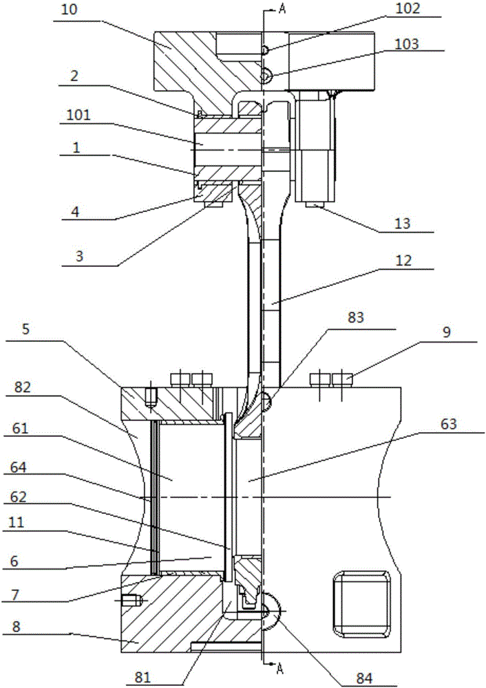
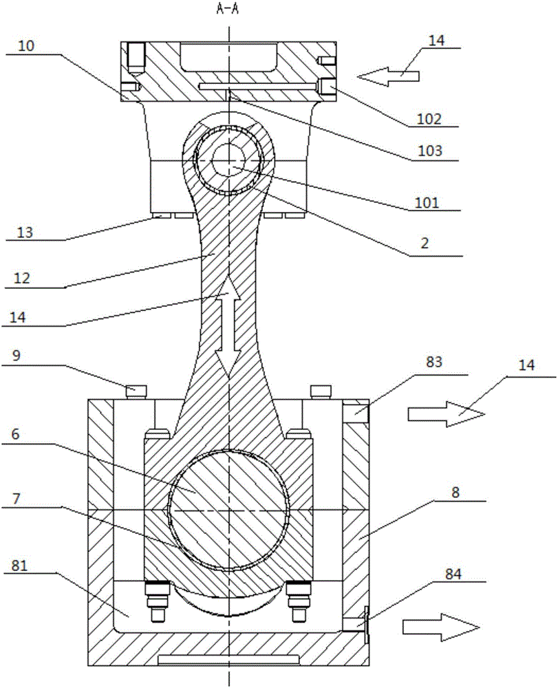
The invention provides a fatigue test device for an engine connecting rod part. The fatigue test device comprises a piston pin boss, a pin boss hole is formed in the piston pin boss, the inner diameter of the pin boss hole is matched with a pin tile, the inner diameter of the pin tile is matched with a piston pin, the piston pin is matched with the small end of a test part, the big end of the test part is matched with a straight shaft of a connecting rod, the straight shaft of the connecting rod is matched with the inner diameter of a shaft tile, and the outer diameter of the shaft tile is matched with the interior of a connecting rod shaft support. According to the fatigue test device for the engine connecting rod part, the structure is compact, and little space is occupied; steel structure design and high-strength bolts are combined, the strength and the rigidity are high; the shaft diameter of the connecting rod straight shaft and the shaft diameter of the piston pin can be adjusted, replacement is conveniently conducted according to the size of the diameters of a big end hole and a small end hole of the test connecting rod to keep the integral composition of the whole device invariable, the repeated utilization rate of the connecting rod part test device is increased, the university is guaranteed, the application range is widened, and economic input is effectively reduced.

Description

technical field [0001] The invention belongs to the field of engine tests, in particular to a fatigue test device for engine connecting rod parts. Background technique [0002] As a key moving component in the engine body structure, the connecting rod part bears the effects of reciprocating inertial force, rotational inertial force, and gas pressure in the cylinder during work. The rod body performs uninterrupted reciprocating plane swing, resulting in local stretching of the connecting rod , compression, bending and other compound stress alternating action. The complex stress action and special motion form are likely to cause local fracture, instability, bolt fracture, bearing bush damage and other failures of the connecting rod parts. Therefore, the effective guarantee of structural strength and fatigue reliability of connecting rod components is the key to engine design. [0003] In the development of new products, the weak link of the structural fatigue strength of the...

Claims


Application Information

Patent Timeline
Patent Type & Authority Applications(China)
IPC IPC(8): G01M13/00
CPCG01M13/00
Inventor 狄建兵侯晔星张丽强王延荣闫玮王昊马宁王龙韬
Owner CHINA NORTH ENGINE INST TIANJIN
Why Eureka
Try Eureka