Eureka AIR delivers breakthrough ideas for toughest innovation challenges, trusted by R&D personnel around the world.

Method and system for monitoring speed of unmanned plane

A technology of speed monitoring and drones, applied in the field of drones, can solve the problems of high processor chip requirements and complicated calculation process, and achieve the effect of simple calculation, small calculation amount and accurate results

Active Publication Date: 2016-12-07
SHENZHEN HIGHGREAT TECH DEV CO LTD
View PDF7 Cites 18 Cited by
  • Summary
  • Abstract
  • Description
  • Claims
  • Application Information

AI Technical Summary

Benefits of technology

This patented technology allows for precise measurement of flying objects' movements over time without relying solely upon visual observation or measuring physical properties such as pressure waves caused when an object passes near another body during flight. It uses images captured at different times together to determine how fast they move around within space. By analyzing these measurements it provides valuable insights into their movement patterns and impacts on various systems like pilots vehicles (such as airplanes).

Problems solved by technology

This patented technology describes how it uses cameras or other sensors to monitor flying drones' movements during autonomous navigation (autonomic control). However, current methods require complex calculations that are time-consuming when compared against real world performance capabilities such as verticality over distance.

Method used


Image

  • Method and system for monitoring speed of unmanned plane
  • Method and system for monitoring speed of unmanned plane
  • Method and system for monitoring speed of unmanned plane

Examples


Embodiment 1

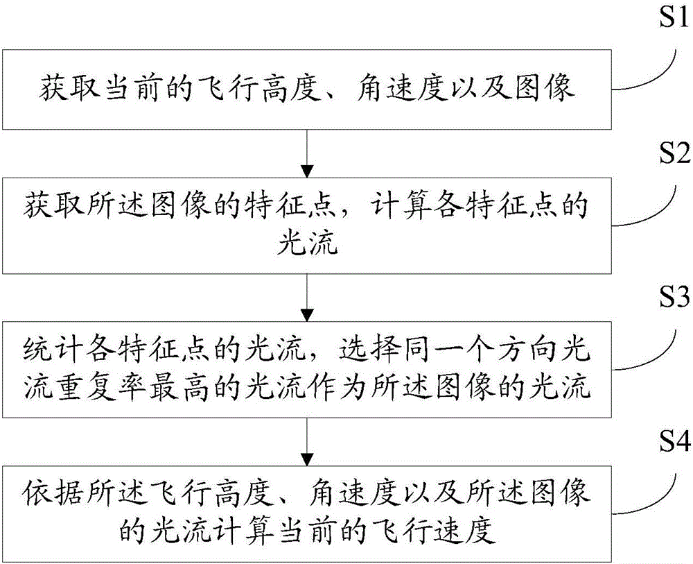
[0077] Please refer to figure 2 , Embodiment 1 of the present invention is:

[0078] A method for monitoring the speed of an unmanned aerial vehicle, comprising:

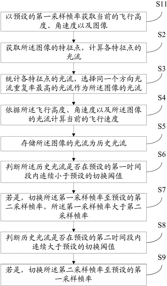
[0079] Obtain the current flying height, angular velocity and image with the preset first sampling frame rate; specifically, measure the flying height through the ultrasonic altimetry module, and measure the angular velocity through the three-axis angular velocity measurement module; the camera includes But not limited to the network camera module, the image direction of the camera is consistent with the direction of the drone, the imaging plane of the camera is parallel to the horizontal plane of the drone, and the optical axis of the camera is perpendicular to the plane of the drone and faces the ground. Shooting; the ultrasonic altimetry module includes but is not limited to a single-head ultrasonic module that integrates sending and receiving and a double-head ultrasonic that separates sending and receiving; t...

Embodiment 2

[0088] Please refer to Figure 4 , the second embodiment of the present invention is:

[0089] An unmanned aerial vehicle speed monitoring system corresponding to the unmanned aerial vehicle speed monitoring method of the first embodiment above, comprising:

[0090] An acquisition module 1, configured to acquire the current flight height, angular velocity and image at a preset first sampling frame rate;

[0091] The optical flow calculation module 2 is used to acquire the feature points of the image, and calculates the optical flow of each feature point; the optical flow calculation module 2 includes: a first acquisition module 21, which is used to acquire the described image using the FAST corner detection algorithm. The position and the feature value of each feature point of the image; the second acquisition module 22, for adopting the FAST corner detection algorithm to obtain the position and feature value of each feature point in the previous frame image; calculation modu...


PUM


Abstract

The invention provides a method and system for monitoring the speed of an unmanned plane, and the method comprises the steps: obtaining the current flight altitude and angular velocity and an image; obtaining feature points of the image, and calculating the optical flow of each feature point; carrying out the counting of the optical flows of all feature points, and selecting the optical flow with the maximum optical flow repetitive rate in the same direction as the optical flow of the image; and calculating the current flight velocity according to the current flight altitude and angular velocity and the optical flow of the image. The invention also relates to a system corresponding to the above method. The method obtains the feature points of the current image through calculation, calculates the optical flows of all feature points, and selects the optical flow with the maximum optical flow repetitive rate in the same direction as the optical flow of the image. Afterwards, the method carries out the calculation of the current flight velocity according to the optical flow of the image and the current flight altitude and angular velocity. The method is simple in calculation, is small in calculation burden, gives consideration to the influence of a plurality of factors, and is precise in calculation result.

Description


Claims


Application Information

Patent Timeline
Owner SHENZHEN HIGHGREAT TECH DEV CO LTD
Why Eureka
Eureka Blog
Learn More