
A method and system for monitoring the speed of an unmanned aerial vehicle

A technology of speed monitoring and drones, applied in the field of drones, can solve the problems of complex calculation process and high requirements for processor chips, and achieve the effect of simple calculation, accurate results and small amount of calculation

Active Publication Date: 2019-04-26
SHENZHEN HIGHGREAT TECH DEV CO LTD
View PDF8 Cites 0 Cited by
  • Summary
  • Abstract
  • Description
  • Claims
  • Application Information

AI Technical Summary

Problems solved by technology

Although the above scheme can estimate the horizontal speed of the drone performing hovering flight, the calculation process is relatively complicated and requires high processor chips.

Method used


Image

  • A method and system for monitoring the speed of an unmanned aerial vehicle
  • A method and system for monitoring the speed of an unmanned aerial vehicle
  • A method and system for monitoring the speed of an unmanned aerial vehicle

Examples


Embodiment 1

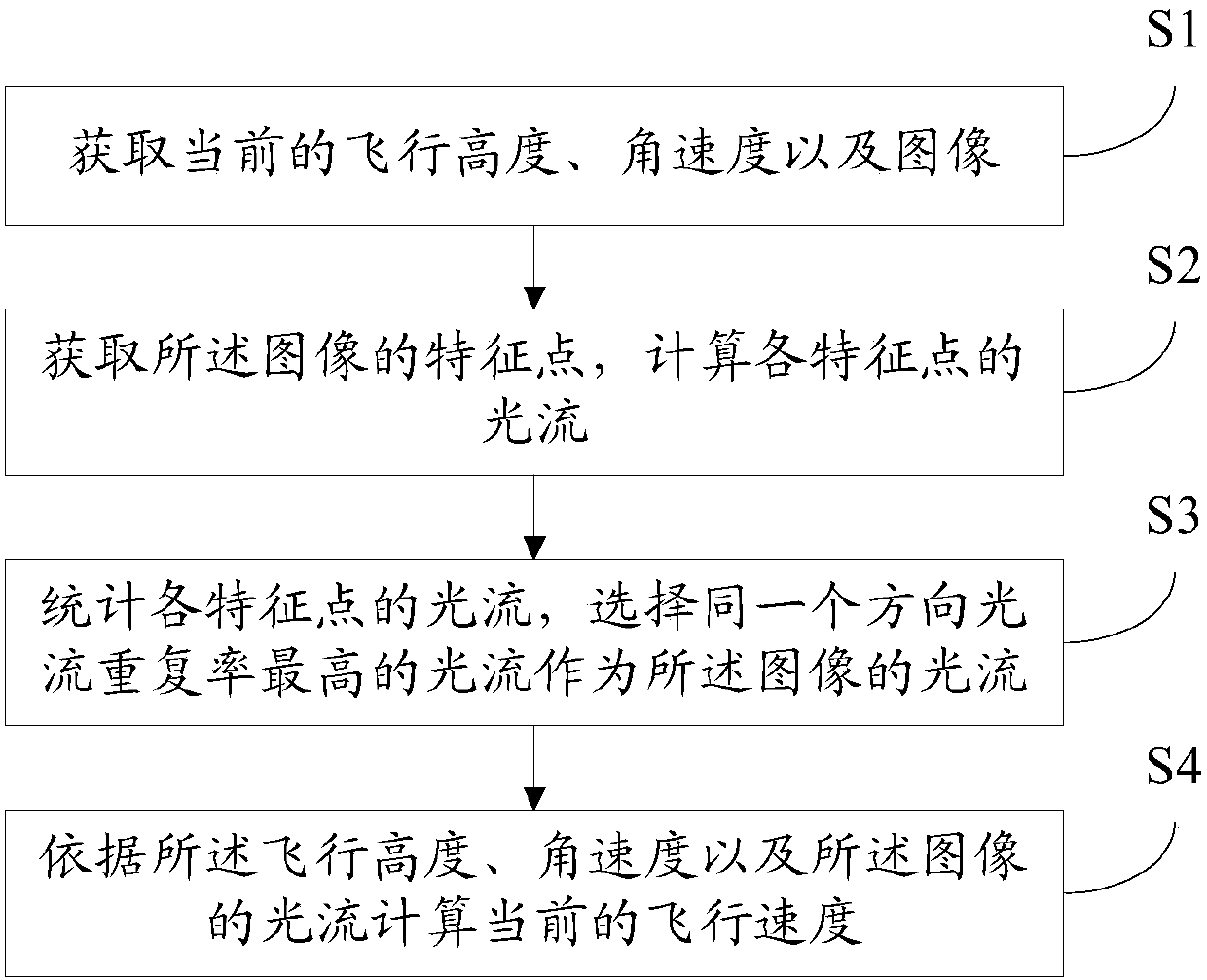
[0077] Please refer to figure 2 , Embodiment 1 of the present invention is:

[0078] A method for monitoring the speed of an unmanned aerial vehicle, comprising:

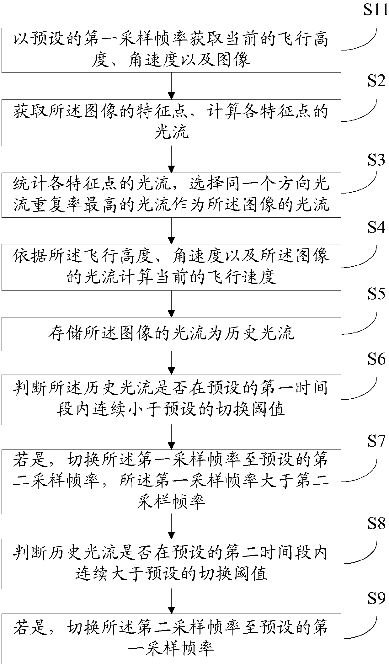
[0079] Obtain the current flying height, angular velocity and image with the preset first sampling frame rate; specifically, measure the flying height through the ultrasonic altimetry module, and measure the angular velocity through the three-axis angular velocity measurement module; the camera includes But not limited to the network camera module, the image direction of the camera is consistent with the direction of the drone, the imaging plane of the camera is parallel to the horizontal plane of the drone, and the optical axis of the camera is perpendicular to the plane of the drone and faces the ground. Shooting; the ultrasonic altimetry module includes but is not limited to a single-head ultrasonic module that integrates sending and receiving and a double-head ultrasonic that separates sending and receiving; t...

Embodiment 2

[0088] Please refer to Figure 4 , the second embodiment of the present invention is:

[0089] An unmanned aerial vehicle speed monitoring system corresponding to the unmanned aerial vehicle speed monitoring method of the first embodiment above, comprising:

[0090] An acquisition module 1, configured to acquire the current flight height, angular velocity and image at a preset first sampling frame rate;

[0091] The optical flow calculation module 2 is used to acquire the feature points of the image, and calculates the optical flow of each feature point; the optical flow calculation module 2 includes: a first acquisition module 21, which is used to acquire the described image using the FAST corner detection algorithm. The position and the feature value of each feature point of the image; the second acquisition module 22, for adopting the FAST corner detection algorithm to obtain the position and feature value of each feature point in the previous frame image; calculation modu...


PUM


Abstract

The invention provides a method and system for monitoring the speed of an unmanned plane, and the method comprises the steps: obtaining the current flight altitude and angular velocity and an image; obtaining feature points of the image, and calculating the optical flow of each feature point; carrying out the counting of the optical flows of all feature points, and selecting the optical flow with the maximum optical flow repetitive rate in the same direction as the optical flow of the image; and calculating the current flight velocity according to the current flight altitude and angular velocity and the optical flow of the image. The invention also relates to a system corresponding to the above method. The method obtains the feature points of the current image through calculation, calculates the optical flows of all feature points, and selects the optical flow with the maximum optical flow repetitive rate in the same direction as the optical flow of the image. Afterwards, the method carries out the calculation of the current flight velocity according to the optical flow of the image and the current flight altitude and angular velocity. The method is simple in calculation, is small in calculation burden, gives consideration to the influence of a plurality of factors, and is precise in calculation result.

Description

technical field [0001] The invention relates to the technical field of unmanned aerial vehicles, in particular to a method and system for monitoring the speed of an unmanned aerial vehicle. Background technique [0002] At present, in the UAV industry, the use of computer vision for speed monitoring has received extensive attention, especially in terms of speed monitoring based on image optical flow algorithms. For example, the Chinese invention patent with the publication number CN102298070B discloses a method for estimating the horizontal velocity of a drone, especially a drone capable of performing hovering flight under automatic driving. The method includes: estimating the continuous The movement of the scene between images and applying a scaling factor as a function of the measured height to the estimated movement, the estimation of the movement consists of periodically and continuously updating a multi-resolution representation of the image type pyramid in different G...

Claims


Application Information

Patent Timeline
Patent Type & Authority Patents(China)
IPC IPC(8): G01P3/36G06T7/246
CPCG01P3/36G06T2207/30212
Inventor 高建民
Owner SHENZHEN HIGHGREAT TECH DEV CO LTD
Learn More