
A Capacitive Voltage Transformer Used in Transient Overvoltage Monitoring System

A technology of transient overvoltage and voltage transformer, which is applied in the direction of voltage divider, measuring current/voltage, instruments, etc., can solve the problems of inability to effectively monitor the transient process of the power system and the inability to monitor the operation status of the power system, and achieve the applicable Wide range, anti-friction static electricity, high working frequency effect

Active Publication Date: 2019-03-08
SHANGHAI MUNICIPAL ELECTRIC POWER CO +3
View PDF6 Cites 0 Cited by
  • Summary
  • Abstract
  • Description
  • Claims
  • Application Information

AI Technical Summary

Problems solved by technology

However, due to the limitation of the total capacity of the system, the sampling frequency of the equipment will not be too high. In addition, due to the frequency response characteristics of the sampling equipment, the current dispatch monitoring system and other system monitoring systems cannot effectively monitor the transient process of the power system. Therefore, it is impossible to comprehensively monitor the operating status of the power system.

Method used

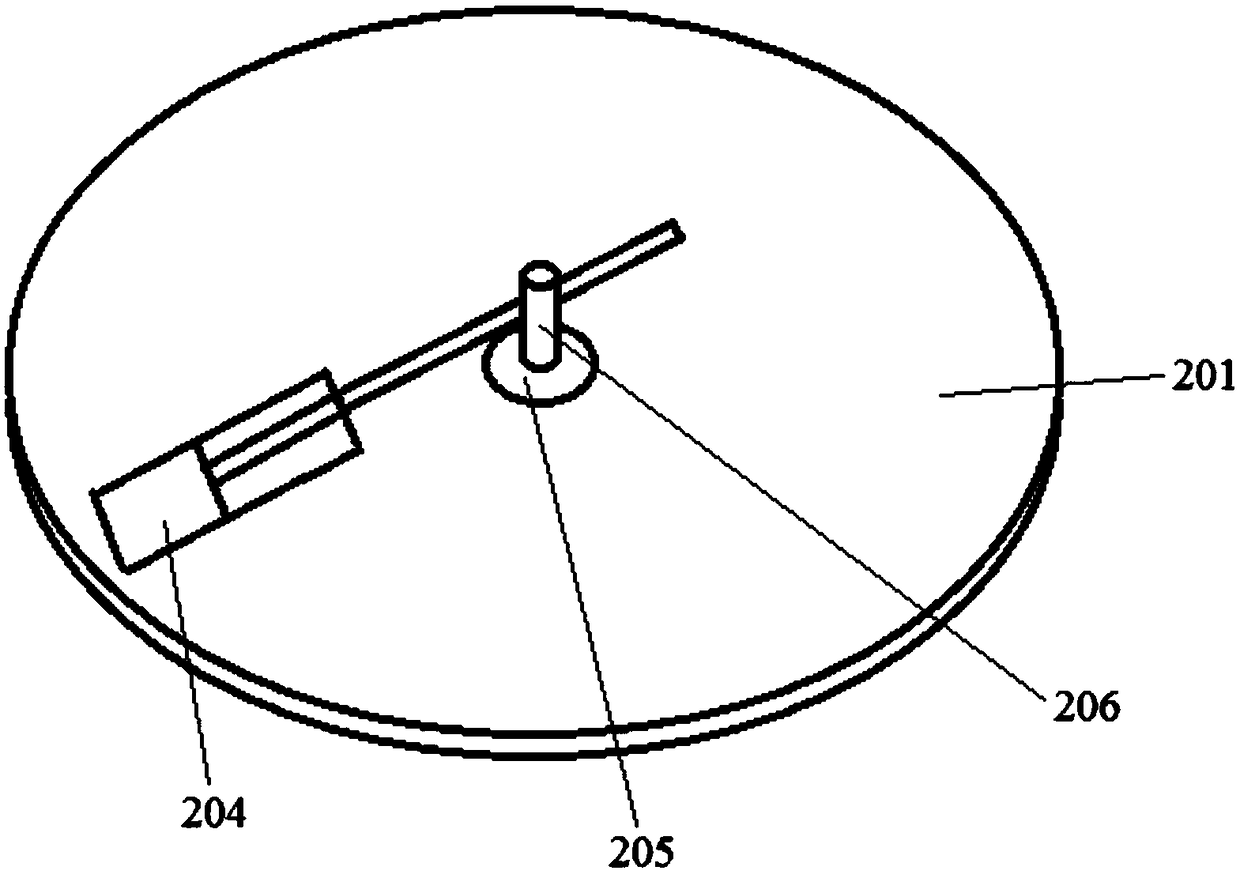
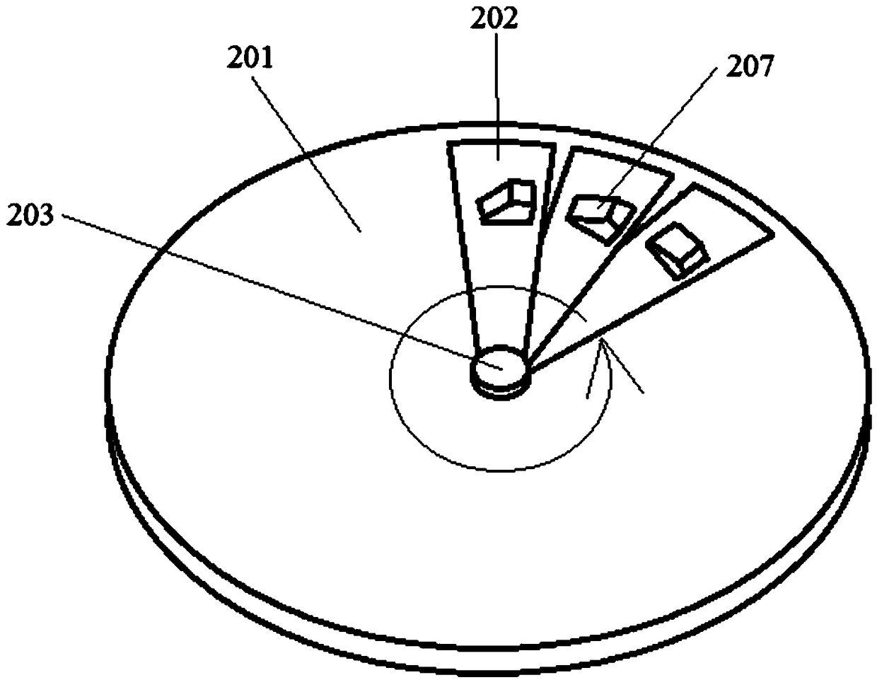

Image

  • A Capacitive Voltage Transformer Used in Transient Overvoltage Monitoring System
  • A Capacitive Voltage Transformer Used in Transient Overvoltage Monitoring System
  • A Capacitive Voltage Transformer Used in Transient Overvoltage Monitoring System

Examples


Embodiment Construction

[0030] The present invention will be described in detail below in conjunction with the accompanying drawings and specific embodiments. This embodiment is carried out on the premise of the technical solution of the present invention, and detailed implementation and specific operation process are given, but the protection scope of the present invention is not limited to the following embodiments.

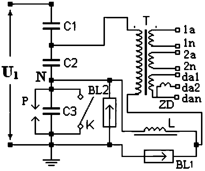
[0031] Such as figure 1 As shown, a capacitive voltage transformer 2 for a transient overvoltage monitoring system includes a high-voltage capacitor C1, a medium-voltage capacitor C2, an intermediate transformer T, a transient overvoltage monitoring unit C3, a grounding switch K, and a compensation reactance L, damper ZD, protection gap P, first arrester BL1 and second arrester BL2, one end of high-voltage capacitor C1 is connected to grid 1, and the other end is respectively connected to one end of medium-voltage capacitor C2 and one end of the primary winding in intermediate transfo...


PUM


Abstract

A capacitive voltage mutual inductor (2) for a transient over-voltage monitoring system comprises a first capacitor (C1), a second capacitor (C2), a third capacitor (C3), an intermediate transformer (T), a transient over-voltage monitoring unit (M), a grounding switch (K), a compensation reactor (L) and a first lightning arrester (BL1). One end of the first capacitor (C1) is connected to a power grid (1), and the other end is respectively connected to one end of the second capacitor (C2) and one end of a primary winding in the intermediate transformer (T). The other end of the second capacitor (C2) is respectively connected to one end of the transient over-voltage monitoring unit (M) and one end of the compensation reactor (L). The other end of the primary winding of the intermediate transformer (T) is respectively connected to the other end of the compensation reactor (L) and one end of the first lightning arrester (BL1). The other end of the transient over-voltage monitoring unit (M) and the other end of the first lightning arrester (BL1) are both grounded. The grounding switch (K) is connected in parallel at the two ends of the transient over-voltage monitoring unit (M). One end of the third capacitor (C3) is connected to the other end of the second capacitor (C2), and the other end of the third capacitor (C3) is grounded. A voltage bearable by the first capacitor (C1) is greater than a voltage bearable by the second capacitor (C2), and the voltage bearable by the second capacitor (C2) is greater than a voltage bearable by the third capacitor (C3).

Description

technical field [0001] The invention relates to the field of electrical engineering, in particular to a capacitive voltage transformer used in a transient overvoltage monitoring system. Background technique [0002] The transient process of the power grid is an important indicator of the operating state of the power grid. At present, there is still a lack of effective measurement or monitoring methods for transient overvoltages (lightning waves, operating wave overvoltages) in the power grid at home and abroad. For newly-built equipment, only some power units in China test the operating overvoltage of the 500kV system before it is officially put into operation. Generally, they conduct transient measurements when switching no-load lines, main transformers, low-voltage reactors or capacitors, as a test Live assessment of new equipment. There are reports of using optical fiber technology for monitoring in foreign countries. [0003] For operating equipment, currently installe...

Claims


Application Information

Patent Timeline
Patent Type & Authority Patents(China)
IPC IPC(8): G01R15/06G01R19/165
CPCG01R15/06G01R19/165
Inventor 邹俭叶洪波李骏金珩司文荣赵文彬赵丹丹周行星黄华
Owner SHANGHAI MUNICIPAL ELECTRIC POWER CO
Learn More