Method and device for generating non-diffracting Airy beam carrying orbital angular momentum

An orbital angular momentum, Airy beam technology, applied in optics, optical components, instruments, etc., can solve the problem of inability to rotate and manipulate particles, and achieve good application prospects and small thermal effects.

Inactive Publication Date: 2016-12-07
ZHEJIANG NORMAL UNIVERSITY
View PDF6 Cites 13 Cited by
  • Summary
  • Abstract
  • Description
  • Claims
  • Application Information

AI Technical Summary

Benefits of technology

In this patented process, an airy particle with unique properties like its own spinning motion or spiraling movement was created by adding certain types of energy called orbitingangular moment (OAM) onto it's surface. These OAM modes were found effective for turning objects around while minimizing any harm caused during their capture. Overall, these technical benefits make them useful tools that could be used in various fields such as Optical Microsystem Technology (OMT).

Problems solved by technology

Technical Problem: The technical problem addressed by this patents relates to finding an effective way to create an Active Beam (AB) type structure called Anairys or Lambdabeam(Blakely), where multiple waves can travel together at once while maintain their original shape when bent around a curved surface like a circle.

Method used


Image

  • Method and device for generating non-diffracting Airy beam carrying orbital angular momentum
  • Method and device for generating non-diffracting Airy beam carrying orbital angular momentum
  • Method and device for generating non-diffracting Airy beam carrying orbital angular momentum

Examples


Embodiment Construction

[0015] In order to enable those skilled in the art to better understand the solutions of the present invention, the technical solutions in the embodiments of the present invention will be described clearly and completely in conjunction with the accompanying drawings in the embodiments of the present invention. Obviously, the described embodiments are only It is a part of the embodiments of the present invention, but not all the embodiments. Based on the embodiments of the present invention, all other embodiments obtained by those of ordinary skill in the art without creative work shall fall within the protection scope of the present invention.

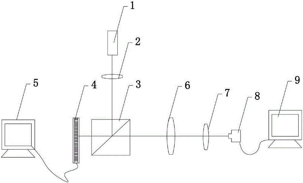
[0016] Reference Figure 1-3 As shown, figure 1 It is a schematic diagram of a device for generating a non-diffraction Airy beam carrying orbital angular momentum produced by the present invention. It includes a laser 1, a collimating beam expander 2, a beam splitter 3, a spatial light modulation 4, a control computer 5, a Fourier lens 6...


PUM


Abstract

The invention discloses a method for generating a non-diffracting Airy beam carrying orbital angular momentum. The method includes the steps of: 1) emitting a Gaussian beam from a laser and collimating and expanding the Gaussian beam; 2) projecting the collimated and expanded Gaussian beam onto a spectroscope to be split; 3) loading a helical cubic phase diagram carrying an orbital angular momentum factor on a spatial light modulator; 4) injecting the split beam into the spatial light modulator with the helical cubic phase diagram to be subjected to phase modulation; 5) performing Fourier transform on the phase-modulated beam through a Fourier lens to obtain a non-diffracting Airy beam carrying the orbital angular momentum. The invention also relates to a device for generating a non-diffracting Airy beam carrying orbital angular momentum.

Description


Claims


Application Information

Patent Timeline
Owner ZHEJIANG NORMAL UNIVERSITY
Why Eureka
Try Eureka