A Method of Using Diffraction Patterns to Calibrate Pinhole Positions in Spatial Filters

A technology of spatial filter and diffraction pattern, applied in instruments, optical components, optics, etc., can solve the problems such as the inability to accurately determine the relative position of the spatial filter and the distortion of the outgoing laser spot, and achieve simple, efficient, practical, accurate calibration, and adjustment. handy effect

Active Publication Date: 2018-12-25
SHANGHAI INST OF OPTICS & FINE MECHANICS CHINESE ACAD OF SCI
View PDF6 Cites 0 Cited by
  • Summary
  • Abstract
  • Description
  • Claims
  • Application Information

AI Technical Summary

Problems solved by technology

[0006] The purpose of the present invention is to solve the current problem that the relative position between the small hole in the spatial filter and the laser focus cannot be accurately determined, resulting in a certain deviation when the laser passes through the hole, which eventually leads to the distortion of the outgoing laser spot. The method of calibrating the pinhole position in the spatial filter by the diffraction pattern is to insert a calibration diaphragm in front of the spatial filter, and use the CCD to observe the far-field diffraction pattern generated by the laser irradiation calibration diaphragm to calibrate the laser focus in the spatial filter. The specific position of the small hole in the device, by adjusting the small hole to make the laser focus coincide with the center of the small hole accurately

Method used


Image

  • A Method of Using Diffraction Patterns to Calibrate Pinhole Positions in Spatial Filters
  • A Method of Using Diffraction Patterns to Calibrate Pinhole Positions in Spatial Filters

Examples


Embodiment Construction

[0026] The present invention will be described in detail below in conjunction with the accompanying drawings and specific implementation examples.

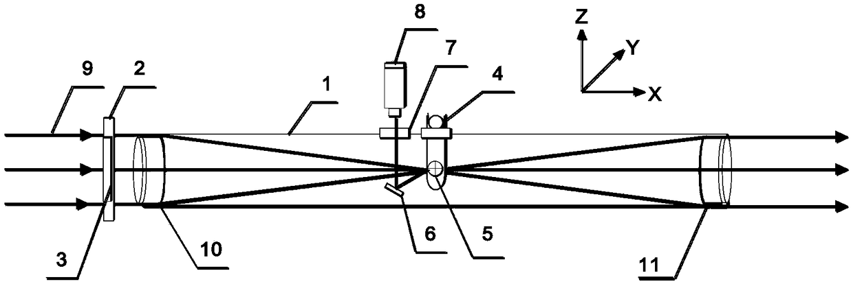
[0027] In order to solve the current problem that the relative position between the small hole in the spatial filter and the laser focus cannot be accurately determined, resulting in a certain deviation when the laser passes through the hole, which eventually leads to the distortion of the exit spot, the present invention proposes a method of using a diffraction pattern to determine A method to mark the location of pinholes in a spatial filter.

[0028] A method for calibrating the position of a small hole in a spatial filter using a diffraction pattern, the specific steps are as follows:

[0029] Step 1, take the cross-section of the small hole 5 in the spatial filter 1 as the YZ plane, fix the calibration diaphragm bracket 2 on the front end of the spatial filter 1 along the X-axis direction, so that the front lens 10 and the re...


PUM


Abstract

The invention discloses a method for calibrating positions of small holes in a spatial filter by means of diffraction patterns. The method comprises the steps that a calibration diaphragm is inserted in front of the spatial filter, and a CCD is used for observing the far-field diffraction pattern generated after laser irradiates the calibration diaphragm for calibrating the specific positions of the small holes in the spatial filter of a laser focal point, so that the laser focal point and the small hole center coincide accurately by adjusting the small holes. The problem that emergent laser spot distortion caused by via hole deviation of laser is effectively solved, and the method has the advantages of being accurate in proofreading, convenient to adjust, simple, efficient, high in practicability and the like.

Description

technical field [0001] The invention relates to the field of space filter, physical optics and large-scale high-power pulsed laser device, in particular to a method for calibrating the position of a small hole in a space filter by using a diffraction pattern. Background technique [0002] In the field of high-power pulsed laser devices, the spatial filter based on the principle of Fourier transform and the design of the "4f" system has the function of filtering and intercepting high-frequency information and plays an image transfer role in the laser transmission process. Therefore, it can effectively protect the laser working material and improve the near-field beam quality of the laser output. Therefore, spatial filters are indispensable in high-power pulsed laser devices, especially in petawatt-level high-power pulsed laser devices. [0003] At present, advanced high-power laser devices will use a large number of spatial filters with different calibers. Generally speaking...

Claims


Application Information

Patent Timeline
Patent Type & Authority Patents(China)
IPC IPC(8): G02B27/46
CPCG02B27/46
Inventor 李文启梁晓燕於亮红郭震彭纯李儒新
Owner SHANGHAI INST OF OPTICS & FINE MECHANICS CHINESE ACAD OF SCI
Why Eureka
Try Eureka