Check patentability & draft patents in minutes with Patsnap Eureka AI!

Liquid crystal display panel

A liquid crystal display panel, display area technology, applied in nonlinear optics, instruments, optics, etc., can solve the problems of loss, installation module structure design, array substrate and color filter substrate separation, etc., to achieve the effect of increasing adhesion

Inactive Publication Date: 2016-12-07
NANJING CEC PANDA LCD TECH
View PDF4 Cites 9 Cited by
  • Summary
  • Abstract
  • Description
  • Claims
  • Application Information

AI Technical Summary

Problems solved by technology

[0006] The separation of the two substrates of most liquid crystal display panels occurs between the black matrix and the color filter substrate. Especially with the increase in the size of the liquid crystal display panel, the unreasonable design of some installation module structures is more likely to cause the array substrate and the color filter substrate to be separated. Membrane substrate detached, resulting in greater loss

Method used


Image

  • Liquid crystal display panel
  • Liquid crystal display panel
  • Liquid crystal display panel

Examples


Embodiment Construction

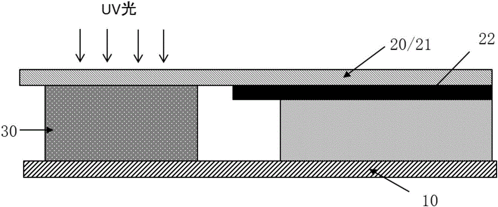
[0020] Liquid crystal display panel of the present invention, as image 3 and Figure 4 As shown, the liquid crystal display panel includes an array substrate 1 and a color filter substrate 2 arranged oppositely, and a liquid crystal (not shown) filled between the array substrate 1 and the color filter substrate 2 . The two substrates are glued together by a frame glue 3 . The liquid crystal display panel is provided with a display area 5 and a peripheral area. The frame glue 3 is arranged between the array substrate 1 and the color filter substrate 3 and is located in the peripheral area.

[0021] The color filter substrate 2 is provided with a glass substrate 21 and a black matrix 21 located under the glass substrate 21 . Part of the black matrix 21 is located in the peripheral area.

[0022] In the peripheral area, the color filter substrate 2 is provided with a black matrix 21 . At the position where the sealant 2 is coated, the black matrix 21 is provided with a plural...


PUM

PropertyMeasurementUnit
Widthaaaaaaaaaa

Abstract

The invention provides a liquid crystal display panel. The liquid crystal display panel comprises an array substrate and a color film substrate which are arranged opposite to each other, and sealant which is used for adhering the array substrate and the color film substrate; the liquid crystal display panel is provided with a display zone and a perimeter zone, and the sealant is positioned in the perimeter zone; the color film substrate is provided with a glass substrate and a black matrix; the black matrix is partially positioned in the perimeter zone; the black matrix is provided with a plurality of slits in the perimeter zone; the sealant is in the zone in which the slits are formed, and is in contact with the glass substrate of the color film substrate. According to the liquid crystal display panel, the slits are formed in the zone of the black matrix at the position where the sealant is coated, and the sealant at the slits is in contact with the glass substrate, so that the adhesion force of the sealant can be increased; therefore, a PCT reliability experiment is qualified.

Description

technical field [0001] The invention relates to a liquid crystal display panel. technical background [0002] like figure 1 As shown, the liquid crystal display panel is composed of an array substrate 10 and a color filter substrate 20 disposed opposite to each other, and a liquid crystal (not shown) filled between the array substrate 10 and the color filter substrate 20 . The array substrate 10 and the color filter substrate 20 are generally bonded together by a sealant 30. In addition to the function of adhering the array substrate and the color filter substrate, the sealant also has the function of supporting the box thickness between the array substrate and the color filter substrate. And sealing to cut off the contact of the liquid crystal molecules with the outside world. [0003] The frame glue is generally coated on the opposite surface of the array substrate and the color filter substrate, and is close to the surrounding edges of the array substrate and the color ...

Claims


Application Information

Patent Timeline
IPC IPC(8): G02F1/1339G02F1/1335
CPCG02F1/1339G02F1/133512
Inventor 李淑君何建国
Owner NANJING CEC PANDA LCD TECH
Features
  • R&D
  • Intellectual Property
  • Life Sciences
  • Materials
  • Tech Scout
  • Unparalleled Data Quality
  • Higher Quality Content
  • 60% Fewer Hallucinations
Learn More