Real-time correction method for pointing direction of radio telescope

A technology for radio telescopes and radio sources, which is applied to the control of electrical components, antennas, and use feedback. It can solve problems that affect the calculation of pointing errors, do not consider the impact of pointing errors, and do not support real-time corrections. It can eliminate pointing errors, The effect of improving pointing accuracy

Active Publication Date: 2016-12-07
SHANGHAI ASTRONOMICAL OBSERVATORY CHINESE ACAD OF SCI
View PDF9 Cites 15 Cited by
  • Summary
  • Abstract
  • Description
  • Claims
  • Application Information

AI Technical Summary

Problems solved by technology

[0010] (1) Scanning in the azimuth and elevation coordinate system causes the azimuth to run too fast at high elevation angles, which affects the calculation of pointing errors, and does not support real-time correction
[0011] (2) The pointing model established on the full pitch and all directions is a fitting result, and there are large errors in some azimuth and pitch angles
[0012] (3) Only the pointing error caused by the azimuth axis and orbital roughness is considered, and the influence of other factors on the pointing error is not considered
[0013] (4) Only the antenna pointing error model based on the least squares vector machine is proposed, which needs further research in terms of kernel function and control parameter selection, and experimental verification of comprehensive environmental factors

Method used


Image

  • Real-time correction method for pointing direction of radio telescope
  • Real-time correction method for pointing direction of radio telescope
  • Real-time correction method for pointing direction of radio telescope

Examples


Embodiment Construction

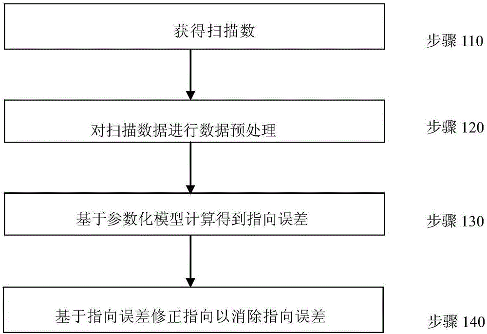
[0043] The method for real-time correction of radio telescope pointing according to the present invention will be further described in detail below in conjunction with the accompanying drawings and specific embodiments.

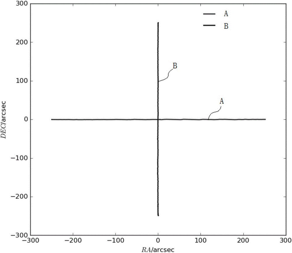
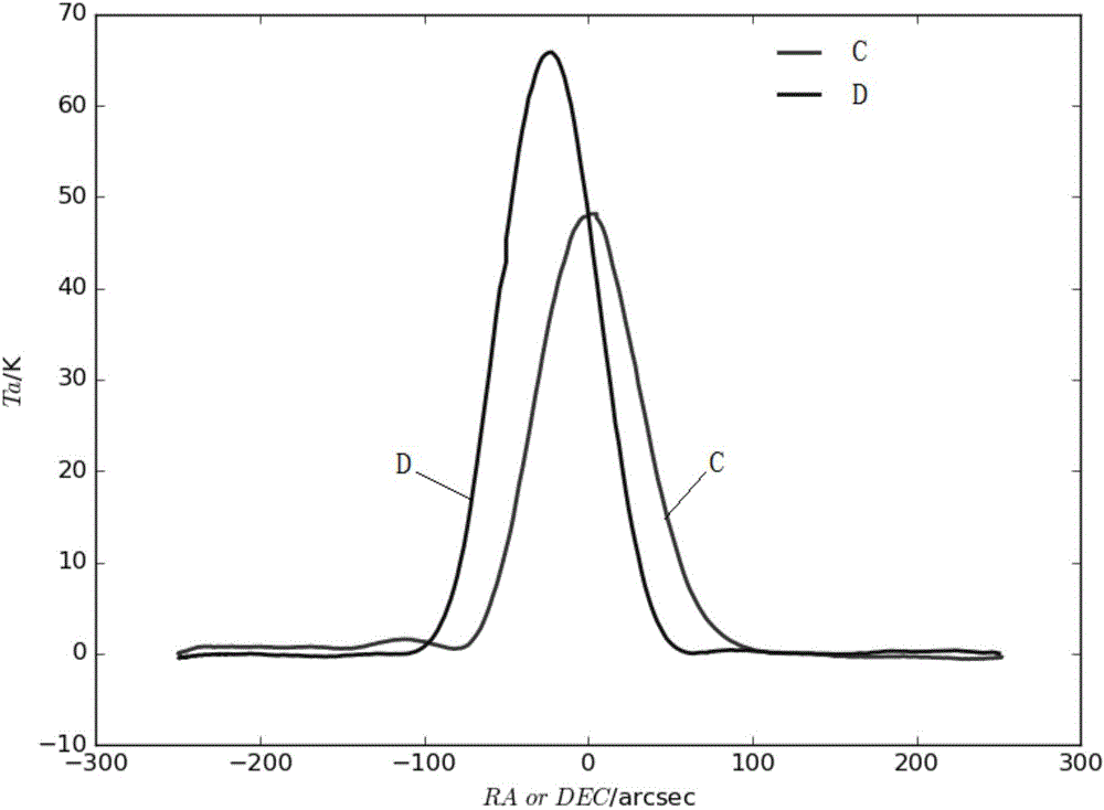
[0044] figure 1 The procedure of the real-time correction method for radio telescope pointing according to the present invention is illustrated in an implementation manner. figure 2 It shows the scanning trajectory in the right ascension and declination directions of the radio telescope pointing real-time correction method according to the present invention in one embodiment, wherein, the abscissa RA / arcsec represents the right ascension data, unit arc second, vertical The coordinate DEC / arcsec represents the declination data, and the unit is arc second. image 3 It shows the right ascension scan data and declination scan data represented by the corresponding antenna pattern in the correction method of the radio telescope pointing real-time correction metho...


PUM


Abstract

The invention discloses a real-time correction method for the pointing direction of a radio telescope. The method includes the following steps that the radio telescope is controlled to carry out at least one time of scanning on a radio source in the right ascensison direction and the declination direction respectively to obtain right ascensison scanning data and declination scanning data; based on a linear function and a Gaussian function, a parameterized model for describing the right ascensison scanning data and the declination scanning data is established, and parameters for describing pointing errors are contained in the parameterized model; the right ascensison scanning data and the declination scanning data are substituted into the parameterized model, pointing errors in the right ascensison direction and the declination direction are acquired through a fitting algorithm, and pointing errors of the orientation and the pitching direction are acquired through coordinate conversion; the pointing direction of the radio telescope is controlled to be corrected based on the pointing errors to eliminate the pointing errors. The real-time correction method for the pointing direction of the radio telescope can be used for real-time correction of the pointing direction of the radio telescope to eliminate the pointing errors in real time, and meanwhile can solve the problem that the orientation operating speed is too high in the high-elevation scanning process under the orientation and a pitching coordinate system.

Description

technical field [0001] The invention relates to a radio telescope pointing correction method, in particular to a radio telescope pointing correction method in real time. Background technique [0002] The deviation of the actual pointing position of the radio telescope when observing the target relative to the theoretical position of the observed target is called pointing error. The electrical axis and mechanical axis of radio telescopes have strict orthogonality and consistency requirements, but due to the influence of various factors such as atmospheric refraction, manufacturing and assembly errors of the telescope, gravity, wind load and temperature load effects, the telescope pointing error will be caused . Pointing accuracy is one of the important indicators to measure the performance of radio telescopes. Its advantages and disadvantages not only affect the single-point observation efficiency of the telescope, but also affect the accuracy of imaging observations. Among...

Claims


Application Information

Patent Timeline
Patent Type & Authority Applications(China)
IPC IPC(8): G05D3/12H01Q3/00
CPCG05D3/12H01Q3/00
Inventor 董健吴亚军左秀婷蒋甬斌刘庆会
Owner SHANGHAI ASTRONOMICAL OBSERVATORY CHINESE ACAD OF SCI
Why Eureka
Try Eureka