Telescope system

a telescope and system technology, applied in the field of telescope systems, can solve the problems of increasing increasing the deformation of the antenna body, etc., and achieve the effect of improving the directivity of the telescope system

Inactive Publication Date: 2007-05-03
MITSUBISHI ELECTRIC CORP
View PDF4 Cites 12 Cited by
  • Summary
  • Abstract
  • Description
  • Claims
  • Application Information

AI Technical Summary

Benefits of technology

[0012] The invention has been devised in view of such solve the problems described above and intends to provide a mechanism for detecting a force, which a main reflector unit and a pedestal unit rece

Problems solved by technology

When the aperture of the antenna is increased, deadweight deformation of the antenna increases and thermal deformation due to the solar radiation and deformation due to the wind pressure increase.
Thus, it is difficult to obtain high pointing and tracking accuracy.
The deformation due to the wind pressure is the main cause of such kinds of deformation.
However, actually, the pedestal affected by the wind force is deformed.
In the conventional large telescope system, the deformation of the pedestals and the like is not taken into account and a

Method used


Image

  • Telescope system
  • Telescope system
  • Telescope system

Examples


first embodiment

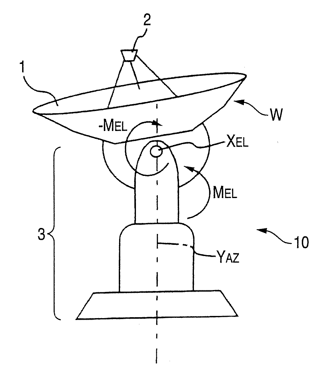
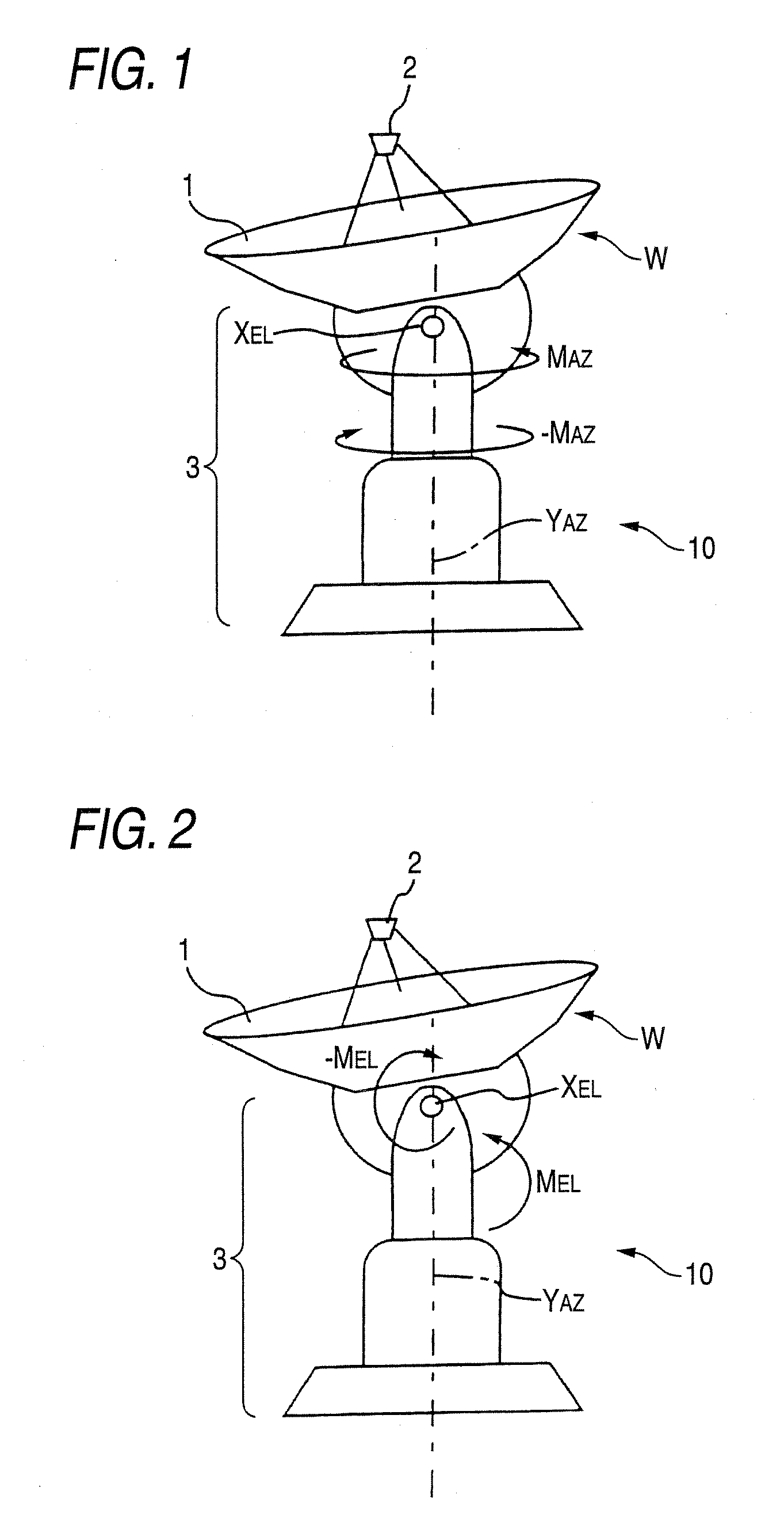
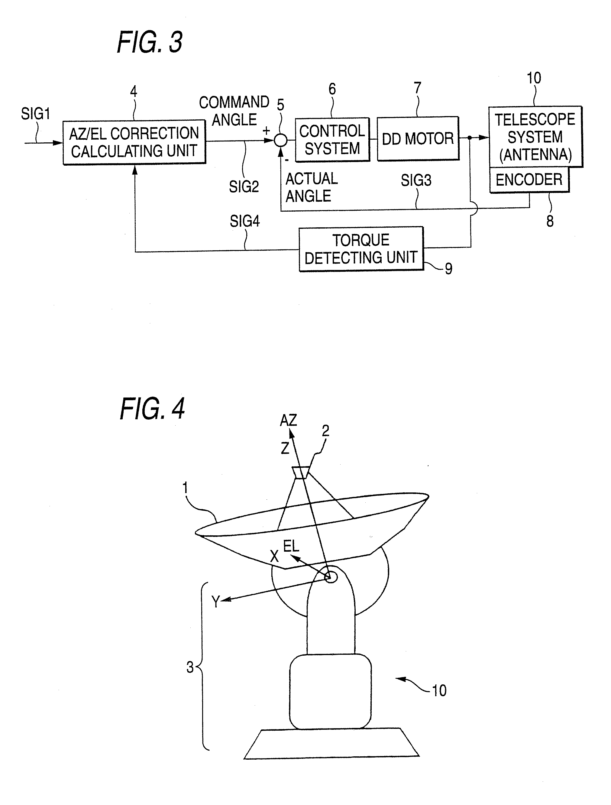
[0024] A wind force metrology of a telescope system according to a first embodiment of the invention will be explained with reference to FIGS. 1 to 7. FIG. 1 is a schematic diagram showing a state in which, for example, a telescope system 10 is subjected to a moment on an AZ axis by the wind force to be in torsion deformation. The telescope system 10 includes a main reflector 1, a sub-reflector 2, and a pedestal unit 3. XEL represents an EL driving shaft, YAZ represents an AZ driving shaft, and W represents a direction of the wind. On the AZ axis and EL axis, motors that drive the respective shafts and encoders that detect rotating positions of the motors are provided (the motors and the encoders are not shown in the figure).

[0025] In FIG. 1, since the telescope system receives the wind in the W direction, a moment MAZ is applied on the AZ axis of the telescope system. At this point, the telescope system causes the motor to output a force MAZ for canceling the moment MAZ on the AZ ...

second embodiment

[0044] A telescope system according to a second embodiment of the invention will be explained with reference to FIG. 8. In FIG. 8, components identical with or equivalent to those in FIG. 3 (the first embodiment) are denoted by the identical reference numerals and signs. The telescope system in FIG. 8 is different from the telescope system in FIG. 3 in that an AZ / EL correction calculating unit 11 is constituted by a computer mounted with an artificial intelligence that performs AZ / EL correction calculation on the basis of accumulated data. A method of calculating a wind force correcting torque in the second embodiment is the same as that described in the first embodiment (FIG. 5). The telescope system can obtain, after entering an operation stage, an enormous amount of data (empirical rules) concerning a wind force correcting torque and a relation between a direction and a pointing (directivity) error of the telescope system. Thus, the artificial intelligence, which updates, using t...


PUM


Abstract

There is provided a telescope system including: a main reflector unit; a pedestal unit that bears the main reflector unit to be rotatable around AZ and EL axes; and a motor that drives the main reflector unit. The telescope system corrects deformation of the main reflector unit and the pedestal unit due to the wind force to improve pointing accuracy of the mina mirror unit and the pedestal unit. The telescope system detects motor torques on the AZ axis and the EL axis, predicts deformation of a telescope due to the wind force from torque signals of the motor torques and a pointing error due to the deformation and feeds back the deformation and the pointing error to AZ and EL command values to perform correction of the pointing error.

Description

BACKGROUND OF THE INVENTION [0001] 1. Field of the Invention [0002] The present invention relates to a telescope system that corrects deformation of a pedestal unit and a main reflector unit due to the wind force to improve pointing accuracy of the pedestal unit and the main reflector unit. [0003] 2. Description of the Related Art [0004] In the field of the radio astronomy, in recent years, there has been an increasing demand for observation of submillimeter waves that are radio waves higher in frequency than millimeter waves. In performing radio astronomical observation at high frequencies, higher accuracy is required for a main reflector (a reflecting mirror) surface of an antenna and pointing and tracking of beams. On the other hand, to improve observation efficiency, an aperture of the antenna is increased and it is desired that observation can be carried out in all kinds of weather night and day. [0005] When the aperture of the antenna is increased, deadweight deformation of th...

Claims


Application Information

Patent Timeline
IPC IPC(8): H01Q3/00
CPCG02B23/16H01Q1/005H01Q3/08
Inventor SOHFUKU, SATORU
Owner MITSUBISHI ELECTRIC CORP
Why Eureka
Try Eureka