Pressible structure and electronic device having the same

A joint and seat technology, applied in the direction of electrical digital data processing, instruments, digital data processing components, etc., can solve problems such as difficult assembly, increased manufacturing cost, and complex structure

Active Publication Date: 2016-12-07
PEGATRON
View PDF5 Cites 2 Cited by
  • Summary
  • Abstract
  • Description
  • Claims
  • Application Information

AI Technical Summary

Problems solved by technology

However, this switching mechanism has a complex structure, which increases manufacturing costs and makes assembly difficult.

Method used


Image

  • Pressible structure and electronic device having the same
  • Pressible structure and electronic device having the same
  • Pressible structure and electronic device having the same

Examples


Embodiment Construction

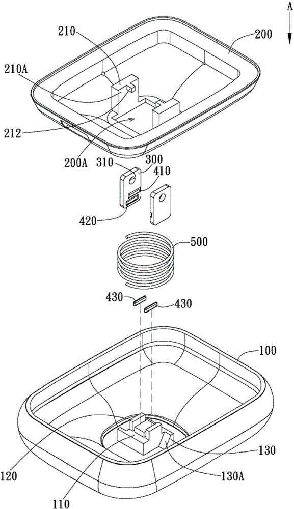
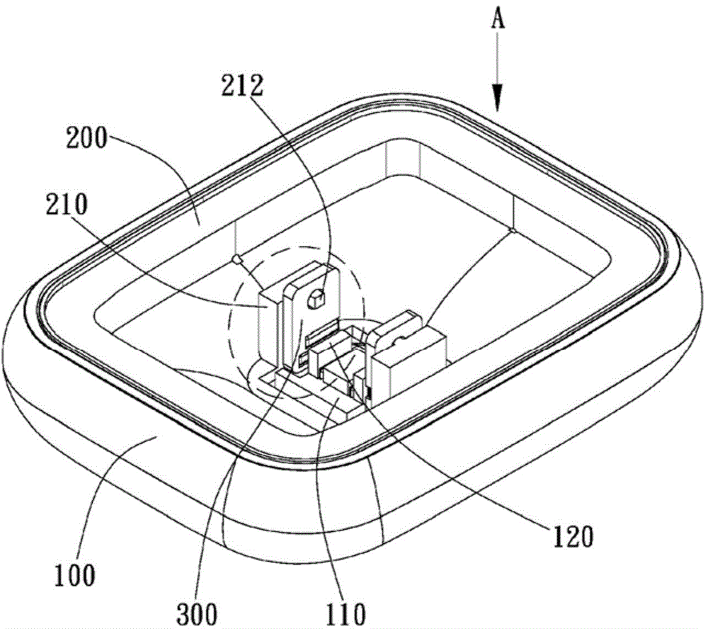
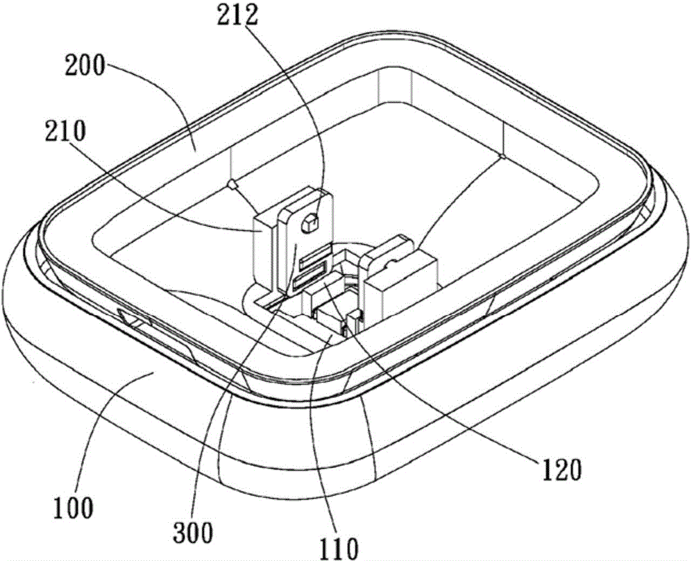
[0024] The invention provides a pressing structure, especially a pressing structure which uses magnetic attraction and repulsion to change the pressing state. The present invention also provides an electronic device with the above pressing structure. In the embodiment of the present invention, the electronic device is preferably an electronic device such as a notebook computer, a watch, a mobile communication device, etc., which can provide different operating states (such as a storage state or a pop-up state) by using a pressing structure, thereby increasing the usability of the electronic device. But not limited to this. Embodiments of the pressing structure and the electronic device of the present invention will be described in detail later with reference to the accompanying drawings.

[0025] Figure 1A and Figure 1B They are an exploded view and a three-dimensional view of a pressing structure according to an embodiment of the present invention, respectively. Such as ...


PUM


Abstract

A pressible structure includes a base having a magnetic portion, a movable unit capable of moving relative to the base along a press direction, a bearing unit disposed on the movable unit, and an elastic unit disposed between the base and the movable unit. The bearing unit has a first magnet and a second magnet disposed along the press direction. When the movable unit moves along with the bearing unit along the press direction and presses the elastic unit and the second magnet moves close to the magnet to create an attraction force, the movable unit is located at a closed position with respect to the base. When the movable unit moves along with the bearing unit along the press direction and presses the elastic unit to move the second magnet away from the magnet and enable the first magnet to move close to the magnet to create a repulsion force, the elastic force can be released to generate a restoring force and drives the movable unit to move relative to the base along a direction reverse to the press direction to a release position.

Description

technical field [0001] The present invention generally relates to a pressing structure, and in particular, the present invention relates to a pressing structure utilizing a magnetic element and an electronic device having the pressing structure. Background technique [0002] The existing common pressing structure is composed of a rotating shaft and a complex engaging mechanism in a mechanical pencil. However, such a pressing structure usually requires sufficient space and is limited to a specific structural shape, which is not conducive to the application in electronic devices that are increasingly shrinking in size. Moreover, the switching structure in the electronic components usually utilizes a combination mechanism such as a hook, a sliding slot, a gear, etc. to realize the switching state by pressing. However, this switching mechanism has a complicated structure, which increases the manufacturing cost and makes the assembly difficult. [0003] Therefore, how to simpli...

Claims


Application Information

Patent Timeline
Patent Type & Authority Applications(China)
IPC IPC(8): G06F1/16
Inventor 方兆裕程依婷姚恺琪
Owner PEGATRON
Why Eureka
Try Eureka