Power-off protection method and device

A power-off protection and circuit technology, which is applied in the field of power-off protection methods and devices, can solve problems such as equipment failure to start automatically, energy waste, safety accidents, etc., and achieve the effect of not affecting work efficiency

Inactive Publication Date: 2016-12-07
PANAN JIARUN ELECTRICAL APPLIANCE CO LTD
View PDF0 Cites 5 Cited by
  • Summary
  • Abstract
  • Description
  • Claims
  • Application Information

AI Technical Summary

Problems solved by technology

Although the addition of a self-locking device reduces the labor intensity of the fingers, there are the following potential safety hazards: when the self-locking is not released, the switch button is always in the closed state. At this time, if the power supply is restored after a power failure, the power tool will be automatically started. Cause energy waste, and even cause safety accidents
In order to solve this problem, technicians in related fields have also developed various types of power-off protectors, which can prevent the equipment from automatically starting after power-off and power-on. However, most of them have inaccurate control and large errors, especially The device cannot start automatically during normal power failure and abnormal power failure, and the degree of intelligence is limited. In abnormal power failure, such as the millisecond-level power failure gap caused by accidentally touching the plug, the device still cannot start automatically after power-on, which affects normal work

Method used


Image

  • Power-off protection method and device
  • Power-off protection method and device
  • Power-off protection method and device

Examples


Embodiment 1

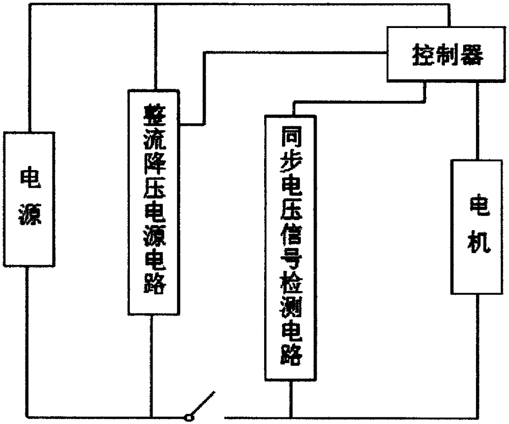
[0036] Such as image 3 and Figure 4 As shown, a power-off protection device includes a controller U1, a thyristor VT, and a rectifying and step-down power supply circuit connected between two ends of the power supply. One end of the power supply is connected to one pole of the motor through a single-pole switch S1, and the other end of the power supply One end is connected to the first anode T1 of the thyristor VT, the second anode T2 of the thyristor VT is connected to the other pole of the motor, the signal input end of the controller U1 is connected to the resistor R3, and the other end of the resistor R3 is connected to the unipolar switch Between S1 and one pole of the motor. The signal input end of the controller U1 is connected to a capacitor C3, and the other end of the capacitor C3 is grounded. A resistor R4 is connected between the signal output end of the controller U1 and the gate G of the thyristor VT. The rectified step-down power supply circuit includes a f...

Embodiment 2

[0039] Such as Figure 5 and Figure 6 As shown, a power-off protection device includes a controller U1, a thyristor VT, and a rectifying and step-down power supply circuit connected between two ends of the power supply. One end of the power supply is connected to one pole of the motor through a single-pole switch S1, and the other end of the power supply One end is connected to the first anode T1 of the thyristor VT, the second anode T2 of the thyristor VT is connected to the other pole of the motor, the signal input end of the controller U1 is connected to a resistor R3, and the other end of the resistor R3 is connected to the thyristor Between the second anode T2 of VT and the motor. The signal input end of the controller U1 is connected to a capacitor C3, and the other end of the capacitor C3 is grounded. A resistor R4 is connected between the signal output end of the controller U1 and the gate G of the thyristor VT. The rectification and step-down circuit includes a fi...

Embodiment 3

[0041] Such as Figure 7 and Figure 8 As shown, a power-off protection device includes a controller U1, a thyristor VT, and a rectifying and step-down power supply circuit connected between two ends of the power supply. In this embodiment, the switch is a bipolar switch K, and one end of the power supply It is connected to the motor through a bipolar switch K, the other end of the power supply is connected to the first anode T1 of the thyristor VT, and the second anode T2 of the thyristor VT is connected to the motor through a bipolar switch K. The synchronous voltage signal detection circuit comprises a first synchronous voltage signal detection circuit and a second synchronous voltage signal detection circuit, the bipolar switch K is located between the first synchronous voltage signal detection circuit and the second synchronous voltage signal detection circuit, and the first synchronous voltage signal The detection circuit includes a resistor R3. One end of the resistor ...


PUM


Abstract

The invention discloses a power-off protection method and device, relates to the technical field of power-off protection, and aims at solving the problems that control of the prior art is inaccurate and the reliability is low. The power-off protection method comprises the steps as follows: power interruption information of a motor is continuously monitored through a power-off protection module; when the power interruption duration is smaller than 80ms, the power-off protection module does not start protection and the motor normally works after being powered up; when the power interruption duration is greater than 80ms, the power-off protection module starts protection, the motor does not work after being powered up, and the power-off protection module returns to initialization; and if a motor switch is in an off state, the motor does not work and the motor can be started by turning off the motor switch and then turning on the motor switch. By the power-off protection method and device, whether the motor is normally powered off or abnormally powered off can be accurately judged; the work efficiency is not affected; and the power-off protection method and device are safe and reliable.

Description

technical field [0001] The invention relates to the technical field of power-off protection, in particular to a method and device for power-off protection with precise control and high reliability. Background technique [0002] At present, whether it is in the construction process or in family life, power outages may occur. If the equipment user forgets or fails to turn off the switch button of the equipment in time, the equipment will be powered on and start working after the power supply is restored, which may cause equipment or personnel. safety accidents, resulting in waste of energy. For electric tools such as angle grinders, in order to avoid pressing the power switch with fingers for a long time during use, people add a self-locking device to the switch button of the electrical appliance and power tool. Press the button of the self-locking device to lock the switch button , At this time, even if you let go of your finger, the power tool will not be powered off. Only ...

Claims


Application Information

Patent Timeline
Patent Type & Authority Applications(China)
IPC IPC(8): H02H7/08H02H11/00
Inventor 陈高洋吴兴和
Owner PANAN JIARUN ELECTRICAL APPLIANCE CO LTD
Why Eureka
Try Eureka