A constant current and constant voltage inductive wireless charging system

A constant current constant voltage, wireless charging technology, applied in the direction of current collectors, electric vehicles, electrical components, etc., can solve the problems of reducing system stability, increasing control costs and complexity, and system instability

Active Publication Date: 2019-01-18
SOUTHWEST JIAOTONG UNIV
View PDF3 Cites 0 Cited by
  • Summary
  • Abstract
  • Description
  • Claims
  • Application Information

AI Technical Summary

Problems solved by technology

Since the equivalent impedance of the load (battery) changes, it is difficult for the system to output the constant current or voltage required by the load under a certain input voltage.
In order to solve this problem, there are usually two methods: 1. Introduce closed-loop negative feedback control in the circuit system, such as adding a controller before the inverter to adjust the input voltage or adopting phase-shift control, or adding a negative feedback control after the secondary coil rectification DC-DC converter; its disadvantage is that it increases the cost and complexity of control and reduces the stability of the system
2. Using frequency conversion control, the system works at two different frequency points to achieve constant current and constant voltage output, but this method will cause frequency bifurcation, resulting in unstable system operation

Method used


Image

  • A constant current and constant voltage inductive wireless charging system
  • A constant current and constant voltage inductive wireless charging system
  • A constant current and constant voltage inductive wireless charging system

Examples


Embodiment 1

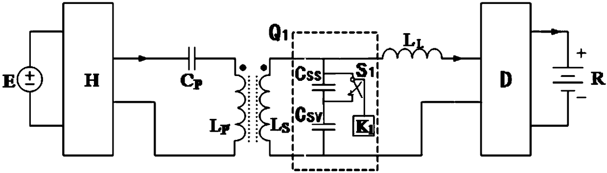
[0090] figure 1 It shows that the first specific implementation of the present invention is a constant current and constant voltage inductive wireless charging system, which is composed of a sending part and a receiving part; the sending part includes: a DC power supply E connected in sequence, a high frequency inverter H, primary compensation capacitor C P and the primary coil L P ; The receiving part includes: the secondary coil L connected in sequence S , constant current and constant voltage switching circuit - Q 1 , Secondary compensation inductance L L , rectification and filtering circuit D and battery load Z; it is characterized in that the secondary coil L S Both ends are connected in parallel with a constant current and constant voltage switching circuit Q 1 , the constant current and constant voltage switching circuit a Q 1 The composition is:

[0091] Secondary constant voltage capacitor C Sv with the secondary additional series capacitor C SS Connect in ...

Embodiment 2

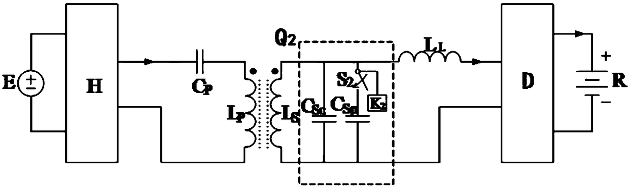
[0103] figure 2 It shows that the second specific implementation of the present invention is a constant current and constant voltage inductive wireless charging system, which is composed of a sending part and a receiving part; the sending part includes: a DC power supply E connected in sequence, a high frequency inverter H, primary compensation capacitor C P and the primary coil L P ; The receiving part includes: the secondary coil L connected in sequence S , constant current and constant voltage switching circuit two Q 2 , Secondary compensation inductance L L , rectification and filtering circuit D and battery load Z; it is characterized in that the secondary coil L S There is a constant current and constant voltage switching circuit two Q in parallel connection at both ends 2 , the constant current and constant voltage switching circuit II Q 2 The composition is:

[0104] Secondary constant current capacitor C SC Parallel to the secondary coil L S Both ends; secon...


PUM


Abstract

A constant current and constant voltage inductive wireless charging system, which consists of a sending part and a receiving part. The receiving part has a constant current and constant voltage switching circuit 1 (Q1). The primary additional series capacitor (CSS) is connected in series and then connected in parallel to both ends of the secondary coil (LS), and the switching switch one (S1) is connected in parallel with the secondary additional series capacitor (CSS), and the control terminal of switching switch one (S1) is connected to The controller one (K1) is connected; or the receiving part has a constant current and constant voltage switching circuit two (Q2). ; The secondary additional parallel capacitor (CSP) is connected in series with the switch 2 (S2) and then connected in parallel to the secondary constant current capacitor (CSC), and the control terminal of the switch 2 (S2) is connected to the controller 2 (K2). It can output constant current and constant voltage irrelevant to the load, and has simple structure and control, stable operation and low manufacturing cost.

Description

technical field [0001] The invention relates to a constant current and constant voltage inductive wireless charging system. Background technique [0002] Inductive wireless power transmission technology provides flexible, safe and reliable power supply to electrical appliances in a non-contact manner through a magnetic field, avoiding safety problems such as contact sparks and leakage in traditional plug-in power transmission systems. The technology is already widely used in built-in medical devices, consumer electronics, lighting and electric vehicles. Among them, the use of inductive wireless power transfer systems for wireless charging of batteries has great development prospects. [0003] In order to achieve safe charging of the battery, prolong the service life of the battery and the number of charge and discharge times, it usually mainly includes two charging stages of constant current and constant voltage. That is, the constant current mode is used at the initial st...

Claims


Application Information

Patent Timeline
Patent Type & Authority Patents(China)
IPC IPC(8): H02J7/00H02J50/10
CPCH02J7/0013H02J7/025
Inventor 麦瑞坤陈阳张友源何正友
Owner SOUTHWEST JIAOTONG UNIV
Why Eureka
Try Eureka