An inductive wireless charging system with variable secondary structure

A secondary structure, wireless charging technology, applied in charging/discharging current/voltage regulation, current collectors, electric vehicles, etc., can solve problems such as reducing system stability, unstable system operation, and increasing inverter capacity requirements

Active Publication Date: 2019-05-31
SOUTHWEST JIAOTONG UNIV
View PDF3 Cites 0 Cited by
  • Summary
  • Abstract
  • Description
  • Claims
  • Application Information

AI Technical Summary

Problems solved by technology

Since the equivalent impedance of the load (battery) changes, it is difficult for the system to output the constant current or voltage required by the load under a certain input voltage.
In order to solve this problem, there are usually two methods: 1. Introduce closed-loop negative feedback control in the circuit system, such as adding a controller before the inverter to adjust the input voltage or adopting phase-shift control, or adding a negative feedback control after the secondary coil rectification DC-DC converter; its disadvantage is that it increases the control cost and complexity, reduces the stability of the system, and the system will input large reactive power, increasing the inverter capacity requirements
2. Using frequency conversion control, the system works at two different frequency points to achieve constant current and constant voltage output, but this method will cause frequency bifurcation, resulting in unstable system operation

Method used


Image

  • An inductive wireless charging system with variable secondary structure
  • An inductive wireless charging system with variable secondary structure
  • An inductive wireless charging system with variable secondary structure

Examples


Embodiment 1

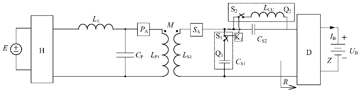
[0131] image 3 As shown, the first specific implementation of the present invention is an inductive wireless charging system with a variable secondary structure, which is composed of a transmitting part and a receiving part. The transmitting part includes a DC power supply E and a high-frequency inverter connected in sequence. H. Primary compensation inductance L 1 , Primary coil compensator P A , Primary coil L P1 ; And in the primary compensation inductance L 1 With primary coil compensator P A The connection point and the high frequency inverter H and the primary coil L P1 A primary compensation capacitor C is connected between the connection points P ; The receiving part includes the secondary coil L connected in sequence S1 , Secondary coil compensator S A , Secondary compensation capacitor C S2 And rectifier filter circuit D, battery load Z.

[0132] The secondary winding compensator S A With secondary compensation capacitor C S2 Connection point and secondary coil L S1 A co...

specific Embodiment approach

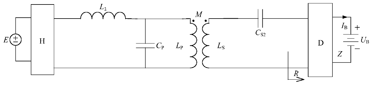
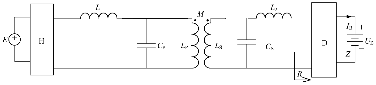
[0152] Figure 4 Shown is the second specific embodiment of the present invention, an inductive wireless charging system with a variable secondary structure, which is composed of a transmitting part and a receiving part. The transmitting part includes a DC power supply E and a high-frequency inverter H connected in sequence. , Primary compensation inductor L 1 , Primary coil compensator P A , Primary coil L P1 ; And in the primary compensation inductance L 1 With primary coil compensator P A The connection point of the high frequency inverter H and the primary coil L P1 A primary compensation capacitor C is connected between the connection points P . The receiving part includes the secondary coil L connected in sequence S1 , Secondary coil compensator S A , Secondary compensation inductance L 2 And rectifier filter circuit D, battery load Z.

[0153] The secondary winding compensator S A With secondary compensation capacitor C S2 Connection point and secondary coil L S1 A constan...


PUM


Abstract

The invention discloses an induction type wireless charging system of a variable secondary structure. A constant current constant voltage switching circuit I and a constant current constant voltage switching circuit II are arranged at a receiving part, the constant current constant voltage switching circuit II is connected in series by virtue of a secondary constant current compensation capacitor (CS1) and a switching switch I, and the control terminal of the switching switch I is connected with a controller I; and a secondary constant current compensation inductance (LCC) and a switching switch II are connected in series, and the control terminal of the switching switch II is connected with the controller I. The invention also discloses a second implementation scheme which is slightly different from the abovementioned scheme in the control terminal. The induction type wireless charging system adopting the structure can output load-independent constant current and constant voltage and is applicable to the condition that multiple charging systems share one inverter, input impedance of the whole process is pure resistive, input of reactive power can be avoided, and system efficiency can be improved.

Description

Technical field [0001] The invention relates to an inductive wireless charging system with a variable secondary structure. Background technique [0002] Inductive wireless power transmission technology uses a magnetic field to provide flexible, safe and reliable power to electrical appliances in a non-contact manner, avoiding the safety problems of contact sparks and leakage in traditional plug-in power transmission systems. This technology has been widely used in fields such as built-in medical devices, consumer electronics, lighting, and electric vehicles. Among them, the use of inductive wireless power transmission systems for wireless charging of batteries has a huge future. [0003] In order to realize the safe charging of the battery and prolong the service life and the number of charging and discharging of the battery, the charging process usually consists of two stages: constant current charging in the early stage and constant voltage charging in the later stage. In the i...

Claims


Application Information

Patent Timeline
Patent Type & Authority Patents(China)
IPC IPC(8): H02J50/10H02J7/00
CPCH02J5/005H02J7/0013H02J7/007H02J7/025
Inventor 麦瑞坤张友源陈阳何正友
Owner SOUTHWEST JIAOTONG UNIV
Why Eureka
Try Eureka