
Wireless charging system and wireless charging method based on primary side controllable capacitance compensation

A technology of capacitance compensation and wireless charging, applied in control/regulation systems, battery circuit devices, current collectors, etc., can solve the problems of difficult design process, increased power loss and cost, and increased system cost and complexity.

Pending Publication Date: 2022-07-29
SOUTH CHINA UNIV OF TECH
View PDF0 Cites 0 Cited by
  • Summary
  • Abstract
  • Description
  • Claims
  • Application Information

AI Technical Summary

Problems solved by technology

[0004] In the first method, adding a DC-DC converter and corresponding control will increase power loss and cost, which is not conducive to simplifying the design; in the second method, a variety of topological structures are used to achieve constant current output and constant voltage output, so that the entire The system is complex and redundant, and the corresponding scope of application will also be limited; the third method needs to achieve constant current output and constant voltage output under the corresponding compensation network by changing the switching frequency. The design process is very difficult and increases the cost of the system. and complexity

Method used


Image

  • Wireless charging system and wireless charging method based on primary side controllable capacitance compensation
  • Wireless charging system and wireless charging method based on primary side controllable capacitance compensation
  • Wireless charging system and wireless charging method based on primary side controllable capacitance compensation

Examples


Embodiment 1

[0022] A wireless charging system based on primary-side controllable capacitance compensation, see figure 1 , the wireless charging system includes a transmitter circuit and a receiver circuit; the transmitter circuit includes a DC power supply 1, a high-frequency full-bridge inverter circuit 2, and a primary side controllable capacitor compensation circuit 3 that is opened and closed by controlling the switch assembly. , a primary side series compensation circuit 4 and an energy transmitting coil 5; the receiving end circuit includes an energy receiving coil 6, a secondary side series compensation circuit 7, a full bridge rectifier filter circuit 8 and a battery load 9, which are connected in sequence.

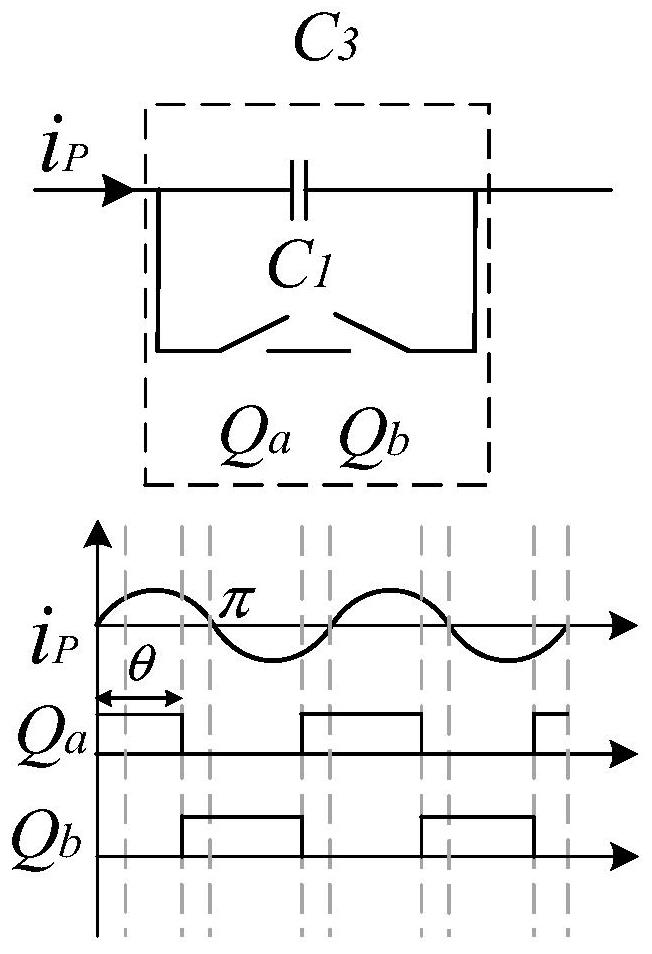
[0023] Wherein, the primary side controllable capacitor compensation circuit 3 includes a primary side compensation capacitor C 1 , switch assembly Q a and switch assembly Q b , the primary side compensation capacitor C 1 The first stage is connected to the first bridge ar...

Embodiment 2

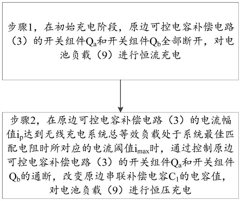
[0027] A wireless charging method based on primary-side controllable capacitance compensation, see figure 2 , the wireless charging method mainly includes the following steps:

[0028] Step 1, in the initial charging stage, the switching component Q of the primary side controllable capacitance compensation circuit 3 a and switch assembly Q b All are disconnected, and the battery load 9 is charged with constant current.

[0029] It can be understood that the wireless charging method of the embodiment of the present invention is implemented based on the wireless charging system of the first embodiment, and can realize the first constant current charging stage and the last constant voltage charging stage of the wireless charging system. The specific charging process is as follows: in the initial charging stage is the constant current output stage, the control switch component Q in the primary side controllable capacitor compensation circuit a , switch assembly Q bare disconn...


PUM


Abstract

The invention provides a wireless charging system and a wireless charging method based on primary side controllable capacitance compensation. The system comprises a transmitting end circuit and a receiving end circuit. The two ends of the primary side controllable capacitance compensation circuit of the transmitting end circuit are connected in parallel with two switch assemblies which are connected in series. In the initial charging stage, all switch assemblies of the primary side controllable capacitance compensation circuit are disconnected, and constant-current charging is carried out on a battery load; and when the amplitude of the primary side current reaches a current threshold value corresponding to the condition that the total equivalent load of the system is located at the optimal matched resistance of the system, the capacitance value of the primary side series compensation circuit is changed by controlling the conduction of a switch assembly of the primary side controllable capacitance compensation circuit, and constant-voltage charging is carried out on the battery load. According to the wireless charging system based on primary side controllable capacitance compensation, the working frequency is fixed, the frequency bifurcation phenomenon does not occur, and the wireless charging system is stable and reliable.

Description

technical field [0001] The present invention relates to the technical field of wireless power transmission, and more particularly, to a wireless charging system and a wireless charging method based on primary side controllable capacitance compensation. Background technique [0002] Inductive wireless power transmission technology is more and more popular in research because of its advantages of safety, stability, flexibility and convenience, electrical and mechanical isolation. It can work in harsh environments such as underwater and mines, and is also widely used in wireless power supply and battery charging, such as electric vehicles, underwater exploration, underground mines, aerospace, implantable medicine, LED lighting, mobile phones Wireless charging of batteries, wireless charging of electric vehicles, etc. These technologies all rely on the charging of the battery, and the charging process of the battery mainly goes through two stages of constant current charging an...

Claims


Application Information

Patent Timeline
IPC IPC(8): H02J7/00H02J50/12H02M3/335H02M7/5387H02M1/088
CPCH02J7/007H02J50/12H02M3/33523H02M7/53871H02M1/088H02J2207/20
Inventor 黄智聪秦甜康浩岚
Owner SOUTH CHINA UNIV OF TECH
Learn More