A constant-current and constant-voltage inductive wireless charging system with three-coil structure

A constant current and constant voltage, wireless charging technology, applied in current collectors, electric vehicles, electrical components, etc., can solve problems such as increasing control cost and complexity, difficulty in outputting constant current or voltage of the load, and unstable system operation.

Active Publication Date: 2020-02-21
SOUTHWEST JIAOTONG UNIV
View PDF5 Cites 0 Cited by
  • Summary
  • Abstract
  • Description
  • Claims
  • Application Information

AI Technical Summary

Problems solved by technology

Since the equivalent impedance of the load (battery) changes, it is difficult for the system to output the constant current or voltage required by the load under a certain input voltage.
In order to solve this problem, there are usually two methods: 1. Introduce closed-loop negative feedback control in the circuit system, such as adding a controller before the inverter to adjust the input voltage or adopting phase-shift control, or adding a negative feedback control after the secondary coil rectification DC-DC converter; its disadvantage is that it increases the cost and complexity of control and reduces the stability of the system
2. Using frequency conversion control, the system works at two different frequency points to achieve constant current and constant voltage output, but this method will cause frequency bifurcation, resulting in unstable system operation

Method used


Image

  • A constant-current and constant-voltage inductive wireless charging system with three-coil structure
  • A constant-current and constant-voltage inductive wireless charging system with three-coil structure
  • A constant-current and constant-voltage inductive wireless charging system with three-coil structure

Examples


Embodiment Construction

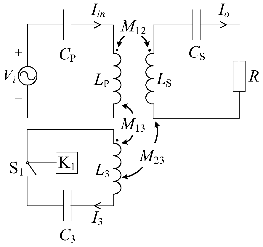
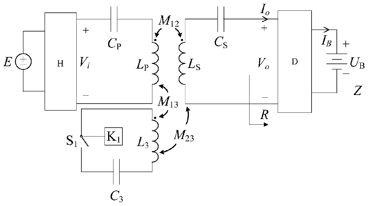
[0072] figure 2 As shown, the specific embodiment of the present invention is a constant current and constant voltage inductive wireless charging system with a three-coil structure, which is composed of a sending part, a receiving part and a constant current and constant voltage switching part. The input of the high frequency inverter H The terminal is connected to the DC power supply E, and its output terminal is connected in series with the primary compensation capacitor C P Then access the primary coil L P Constitute the sending part; the composition of the receiving part is: the rectification filter circuit D input terminal and the secondary coil L S connected in series with the secondary compensation capacitor C S ; The output terminal of the rectification filter circuit D is connected to the battery load Z. The constant current and constant voltage switching section has a primary coil L with p and the secondary coil L S The third coil L constituting the mutual indu...


PUM


Abstract

The invention discloses a constant-current constant-voltage inductive wireless charging system of triple-coil structure, having a transmitting portion, a receiving portion and a constant current constant voltage switching portion. The input end of high-frequency inverter H is connected with direct-current power source E, the output end of the high-frequency inverter H is serially connected with primary compensating capacitor CP and is then connected to secondary coil LP to form the transmitting portion; in the composition of the receiving portion, the input end of rectifier filter circuit D isconnected with secondary coil LS, and secondary compensating capacitor CS is serially connected between the input end and the secondary coil LS, and the output end of the rectifier filter circuit D is connected with battery load Z. The constant current constant voltage switching portion has third coil L3, the third coil L3, the primary coil LP and the secondary coil LS form a mutual inductance coil, the third coil L3 is serially connected with third coil compensating capacitor C3 and changeover switch I S1, and the control end of the changeover switch I S1 is connected with controller I K1. The constant-current constant-voltage inductive wireless charging system is capable of outputting constant current and constant voltage that are irrelevant to a load, and capable of operating under a frequency point; the constant-current constant-voltage inductive wireless charging system is simple in circuit structure and low in cost, has no need for complex control strategies, and is good in control simplicity, convenience and reliability.

Description

technical field [0001] The invention relates to a constant current and constant voltage inductive wireless charging system. Background technique [0002] Inductive wireless power transfer technology is a new type of power supply technology that uses soft media such as magnetic fields to realize non-contact power transmission. It is widely used in medical, consumer electronics, water Power supply, electric vehicle charging and rail transit and other fields. Among them, the use of inductive wireless power transmission technology to wirelessly charge the battery avoids the disadvantages of contact sparks and plug aging in the traditional plug-in system, and has a great development prospect. [0003] In order to achieve safe charging of the battery, prolong the service life of the battery and the number of charge and discharge times, it usually mainly includes two charging stages of constant current and constant voltage. That is, the constant current mode is used at the initia...

Claims


Application Information

Patent Timeline
Patent Type & Authority Patents(China)
IPC IPC(8): H02J7/00H02J50/10
Inventor 麦瑞坤陈阳寇志豪何正友
Owner SOUTHWEST JIAOTONG UNIV
Why Eureka
Try Eureka