Reversible current mirror and use thereof in bidirectional communication

A two-way communication, current mirror technology, applied in the direction of logic circuit coupling/interface, logic circuit, electrical components, etc. using field effect transistors, can solve the problem of contactor error-prone

Active Publication Date: 2018-01-26
THYSSENKRUPP PRESTA AG +1
View PDF9 Cites 0 Cited by
  • Summary
  • Abstract
  • Description
  • Claims
  • Application Information

AI Technical Summary

Problems solved by technology

However, these contactors are prone to error due to the low voltage applied

Method used


Image

  • Reversible current mirror and use thereof in bidirectional communication
  • Reversible current mirror and use thereof in bidirectional communication
  • Reversible current mirror and use thereof in bidirectional communication

Examples


Embodiment Construction

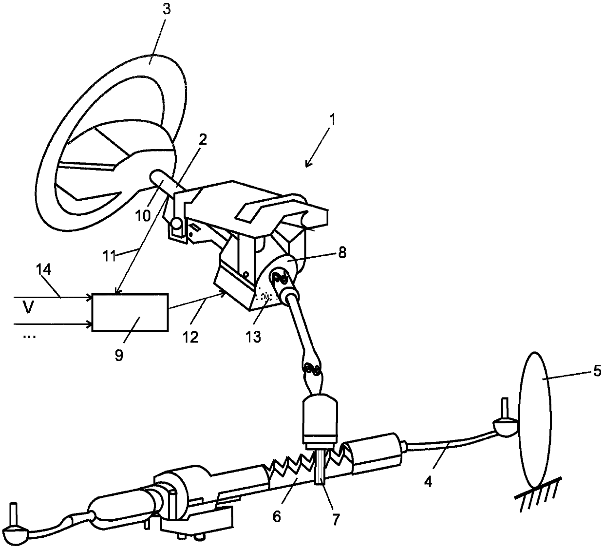
[0019] exist figure 1 In , an electromechanical power steering device 1 is schematically shown having a steering shaft 2 connected to a steering wheel 3 intended to be operated by the driver. The steering rack bar 4 is connected in known manner to steered wheels 5 of the motor vehicle. The rotation of the steering shaft 2 causes an axial displacement of the steering rack 6 via the pinion 7 , which is connected to the steering shaft 2 in a torque-resistant manner. The electromechanical power steering system 1 has a motor housing 8 on the steering column side. The motor housing 8 is connected to a control unit 9 which, among other signals, receives a torque signal from a torque sensor 10 via a signal line 11 and sends a corresponding control signal via a signal line 12 to the arrangement Servomotor 13 in housing 8 . The control unit 9 itself receives an input signal, eg vehicle speed, via a supply line 14 . The servo motor 13 is a permanently excited synchronous motor. The ...


PUM


Abstract

The invention discloses a reversible current mirror and use thereof in bidirectional communication. The present invention relates to a current mirror arrangement for duplex bidirectional communicationbetween two circuit units (A, B), said arrangement comprising in each circuit unit (A, B) two identical transistors (34, 34', 35, 35') with their bases (36, 37) connected together and their bases andtheir collectors connected to each other respectively, wherein each of the connections between the bases and the collectors is formed via a MOSFET (38, 39, 40, 41) and the MOSFETs (38, 39, 40, 41) ofboth circuit units (A, B) are connected together, wherein the MOSFETs' parasitic diodes of each circuit unit (A, B) are arranged in opposite direction with respect to the current system.

Description

technical field [0001] The invention relates to a current mirror arrangement having the features of the preamble of claim 1 and an electromechanical motor vehicle power steering arrangement having the features of the preamble of claim 5 . Background technique [0002] Electromechanical steering generally has an electric motor as a servomotor. A servomotor of this design is actuated by a control unit via groups of metal-oxide-semiconductor field-effect transistors (MOSFETs), wherein a total of six MOSFETs are provided for the three phase windings. Each MOSFET switches the assigned phase winding to either the vehicle supply voltage or ground potential. This switching occurs at a higher frequency so that the instantaneous average value is used as the effective voltage in the phase winding. For safety reasons it is known to separate the phase wires in the neutral point of the motor. The split takes place in the Motor Control Unit (MCU), which is controlled with appropriate in...

Claims


Application Information

Patent Timeline
Patent Type & Authority Applications(China)
IPC IPC(8): H02P27/06H02P25/00H03K19/0185G05F3/26
CPCG05F3/26H02P27/06H03K19/018507B62D5/0463G04G3/02H02P9/06
Inventor 佐尔坦·鲍劳尼奥伊
Owner THYSSENKRUPP PRESTA AG
Why Eureka
Try Eureka