Close-distance fixed point restored sound wave forming method and device

A short-range, sonic technology used in transducer circuits, sensors, electrical components, etc.

Inactive Publication Date: 2016-12-07
MERRY ELECTRONICS SUZHOU
View PDF5 Cites 1 Cited by
  • Summary
  • Abstract
  • Description
  • Claims
  • Application Information

AI Technical Summary

Problems solved by technology

In other words, the above-mentioned method is not suitable for applications in closed spaces at close range
Moreover, the huge number of sending components is not only not conducive to the small space, but also greatly increases the manufacturing cost
If the use of sending components is reduced due to space and cost considerations, a compromise must be made to the distortion of the sound, which will affect the quality of the restored sound
[0006] Based on the above reasons, the known technology cannot form a restored sound signal at a short distance

Method used


Image

  • Close-distance fixed point restored sound wave forming method and device
  • Close-distance fixed point restored sound wave forming method and device
  • Close-distance fixed point restored sound wave forming method and device

Examples


Embodiment 1

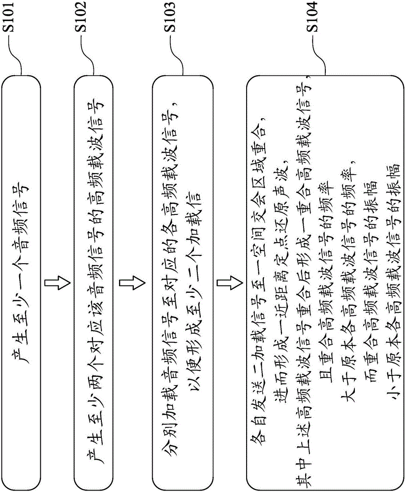
[0051] Embodiment one: see accompanying drawing 1 shown, attached 1 It is a schematic flow chart of the method for forming short-distance fixed-point reduction sound waves in this embodiment.

[0052] In this embodiment, the method for forming short-distance fixed-point reduction sound waves includes the following steps:

[0053] S101 , producing at least one audio signal.

[0054] S102 , generating at least two high-frequency carrier signals corresponding to audio signals.

[0055] S103 , respectively loading audio signals to corresponding high-frequency carrier signals, so as to form at least two loading signals.

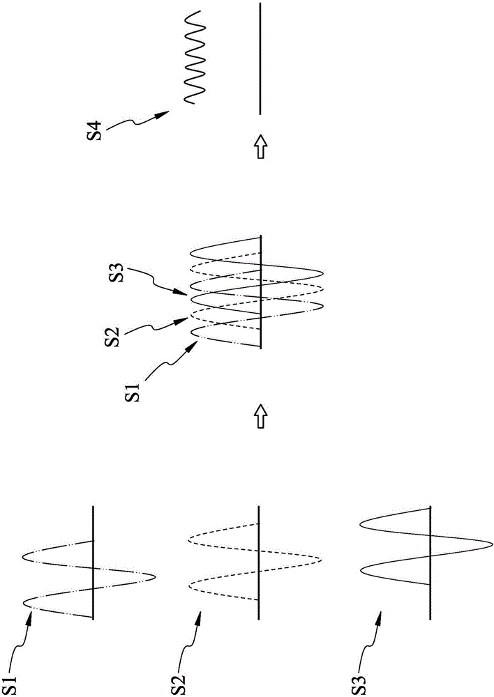
[0056] S104 , each sending two loading signals to overlap in a space intersection area to form a short-distance fixed-point restoration sound wave, wherein the above-mentioned high-frequency carrier signals overlap to form a overlapping high-frequency carrier signal, and the frequency of the overlapping high-frequency carrier signal is great...

Embodiment 2

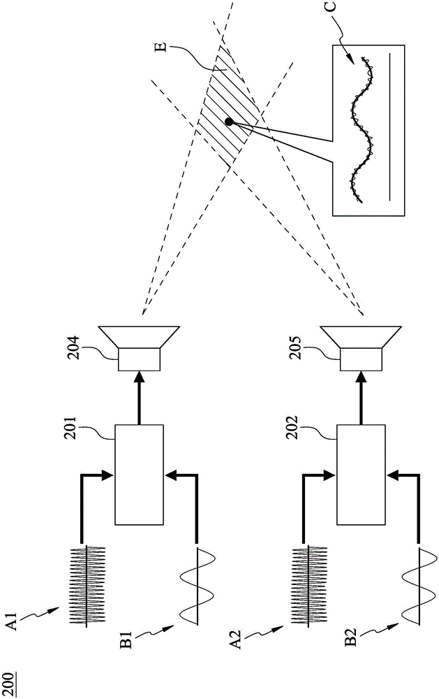
[0066] Embodiment two: see accompanying drawing 3 shown, attached 3 It is the close-range fixed-point reduction sound wave device of this embodiment 200 Schematic diagram; Embodiment 1 describes the method of forming short-distance fixed-point restoration sound waves. This embodiment will be accompanied by a description of the physical structure so that the present invention can be understood more clearly.

[0067] Attached picture 3 Medium and close-range fixed-point reduction sound wave device 200 Include at least two modulators 201 、 202 and bidirectional transmitter 204 、 205 . modulator 201 It is used to receive high frequency carrier signal A1 and audio signal B1 After that, the audio signal B1 Modulated or superimposed and loaded to high frequency carrier signal A1 , forming a loading signal. Similarly, the modulator 202 It is used to receive high frequency carrier signal A2 and audio signal B2 After that, the audio signal B2 Modulate...

Embodiment 3

[0069] Embodiment three: see accompanying drawing 4 Shown, similar to embodiment three, accompanying drawing 4 It is the close-range fixed-point reduction sound wave device of this embodiment 300 schematic diagram. This embodiment uses multiple directional transmitters 204 、 205 、 206 Can restore sound waves at close range C Being better restored, the listener can hear a sound signal with better directivity and less distortion. Accordingly, the close-range fixed-point reduction acoustic wave device disclosed in this embodiment 300 Among them, it is the same as the close-range fixed-point reduction sound wave device of embodiment three 200 The difference lies in the fact that multiple groups set a modulator 203 and directional transmitter 206 。

[0070] Close range fixed-point reduction sound wave device 300 Includes three modulators 201 、 202 、 203 , and three directional transmitters 204 、 205 、 206 . With this configuration, the audio signal B1 ...


PUM


Abstract

The invention provides a close-distance fixed point restored sound wave forming method. The method comprises the steps of generating at least one audio signal; and generating at least two high frequency carrier signals corresponding to the audio signal. The audio signal is loaded to the corresponding high frequency carrier signals, thereby forming at least two loading signals. The loading signals are sent to a space intersection area for superposition, thereby forming a close-distance fixed point restored sound wave. The close-distance fixed point restored sound wave has high directivity, so that a close-distance independently sealed hearing area is formed in the space intersection area, and the sound wave is not interfered by external environments.

Description

technical field [0001] The invention relates to a method and a device for forming short-distance fixed-point reduction sound waves. Background technique [0002] The transmission of sound plays an important role in modern life. The combination of sound and picture brings visual and sensory satisfaction to modern people. Based on modern people's emphasis on personal privacy, it is an important consideration not to disturb or be disturbed by others when listening to music. For reaching above-mentioned purpose, many people build exclusive audio-visual room in their residence. However, it needs to use a certain amount of sound insulation equipment or materials, which is expensive, and not everyone's residence has enough space for building this audio-visual room. Therefore, its application is limited, and the convenience of space is insufficient. [0003] In response to the above problems, some people have thought about how to make the transmission of sound directional in a l...

Claims


Application Information

Patent Timeline
Patent Type & Authority Applications(China)
IPC IPC(8): H04R3/00
Inventor 何桐坤林志忠张瑞成李谋旦
Owner MERRY ELECTRONICS SUZHOU
Why Eureka
Try Eureka