In color displays, light leakage not only degrades the contrast, but also causes undesirable color or
hue shifts, degrading
color reproduction.
In addition to black-state light leakage, viewing angle constraints for typical twisted nematic liquid
crystal displays are exacerbated by a shift in the brightness-
voltage response as a function of viewing angle, due to the inherent
optical anisotropy of the liquid crystal material.
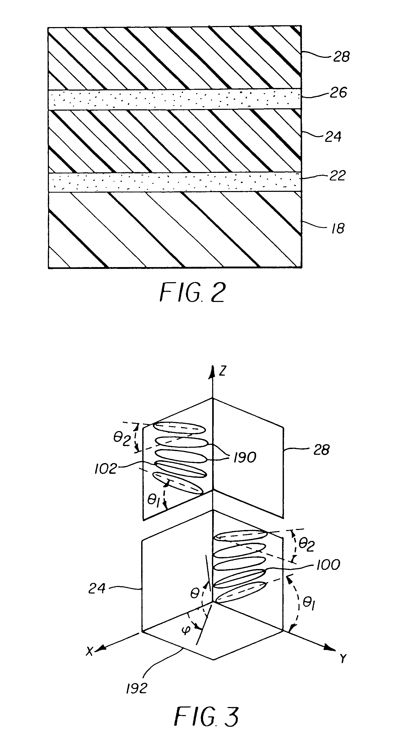
This paper states that “since the second LPP / LCP
retarder film is coated directly on top of the first LCP
retarder film, the
total thickness of the final wide-view
retarder stack is only a few microns thin.” Although such a method provides a very compact optical component, it is difficult to manufacture a compensation film having two LCP
layers whose optical axes are orthogonally oriented.
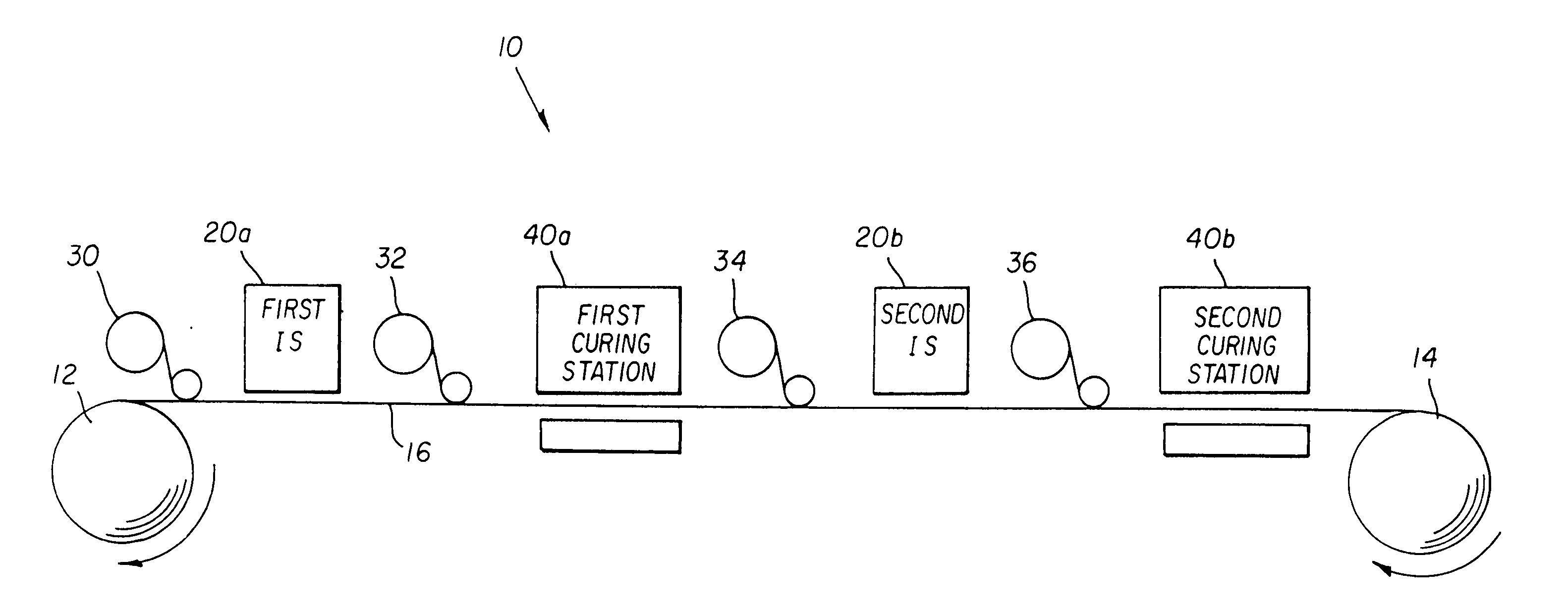
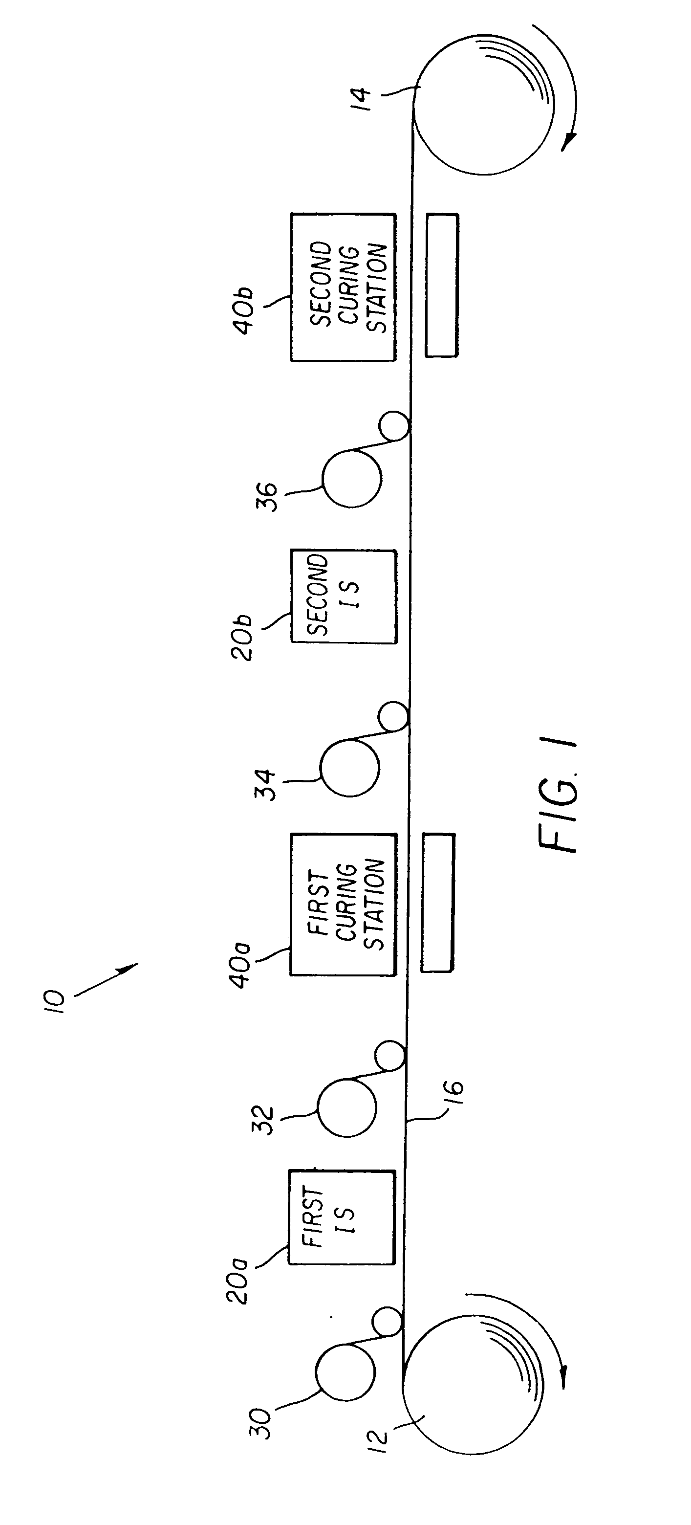
This is a particular challenge where the film substrate is web-fed, such as in a continuous, roll-to-roll manufacturing process.
At such high speeds, the necessary increase in
radiation at desirable wavelengths can easily bring with it an increase in undesirable
radiation levels from other parts of the spectrum.
Of course, the problem of maintaining this tolerance for directional uniformity of polarization is accentuated when irradiating a large scale surface.
However, it can be appreciated that these requirements become particularly difficult to meet as the irradiated surface area, or
exposure zone, increases.
Conventional solutions are as yet poorly suited to the demands for efficiently irradiating a web-fed substrate, where the substrate is moved past the irradiation device at production speeds and the web width exceeds 1 m.
Conventional approaches have not yet provided a suitable solution for achieving this with a web-fed media.
However, there are practical limitations in scaling this type of solution to suit a web-fed substrate having a width dimension of 1 m or larger.
With
irradiance over ranges such as might be supplied using a
medium pressure long-arc Mercury lamp at power levels in the 100-600 W range, conventional, resin-based polarizers would not be well-suited.
Sheet polarizers are not generally capable of handling higher irradiation levels and may quickly deteriorate over a
prolonged exposure period.
However, there are practical size limitations that constrain the use of Brewster plate polarizers for large substrates.
However, similar weight and size constraints also limit the feasibility of this type of solution.
However, such an arrangement would be very costly and bulky, particularly as a solution for a web-fed
exposure system with a large irradiation area.
Hampered by the relative size and weight of these polarizers, such irradiation apparatus are necessarily less efficient in delivering
light energy to the
exposure surface.
Moreover, conventional polarizers using Brewster plates or interference polarizers based on Brewster's angle principles also exhibit a high degree of angular dependency.
Significantly, Brewster plate polarizers such as those shown in the U.S. Pat. No. 5,934,780 and U.S. Pat. Nos. 6,061,138 and 6,307,609 are not optimal for providing a uniform polarization unless highly
collimated light is used.
Otherwise, the Brewster plate
polarizer does not have a well-defined, uniform principal axis of polarization.
Moreover, the Brewster plate
polarizer operates in one direction only; it would not be practical to use Brewster plate polarizers for achieving orthogonal polarization of multiple LPP alignment
layers on a web-fed substrate.
Brewster plate solutions are not compact or practical for use with long-arc lamps, particularly where orthogonal exposure directions must be obtained.
However, sheet polarizers are not robust under conditions of high UV
light irradiance and would deteriorate rapidly.
Thus, it can be seen that it is difficult to obtain efficient polarization of UV-B light (280-320 nm) at relatively
high irradiance levels and for incident light at relatively wide angles of incidence using conventional polarization components and techniques.
However,
wire grid polarization devices are not dimensionally scaled to suit the requirements of applying polarized light over a large exposure zone.
As is noted above, some degree of collimation is necessary for polarizing light, since polarization devices are not typically equipped to
handle wide variations in incident light
divergence.
As is shown in the prior art solutions cited above, achieving polarization over a broad exposure zone, with a tightly controlled direction of polarization, is particularly difficult with
high intensity UV-B
radiation.
It is difficult to obtain a UV-B source that provides polarized UV-B light at reasonable cost.
Moreover,
high heat and
irradiance requirements place considerable demands on filtering and polarization components.
Conventional resin-based sheet polarizers are unlikely to withstand the elevated
irradiance and
high heat conditions.
Brewster plates and interference filters can withstand these conditions but have size and weight disadvantages as well as acceptance angle constraints.
As a further complication, controlling the intensity of radiation energy has been proven to be difficult to achieve and to maintain as a web of material is exposed.
Conventional approaches do not provide a suitable solution for
mass-manufacture fabrication of such a compensation film.
