Directional Microphone

Inactive Publication Date: 2011-06-02
1 LIMITED ST JOHN S INNOVATION CENT
View PDF86 Cites 31 Cited by
  • Summary
  • Abstract
  • Description
  • Claims
  • Application Information

AI Technical Summary

Benefits of technology

[0005]The present invention shows how to overcome the large-size limitation of highly directional low-frequency microphones. The problem of directivity in the prese

Problems solved by technology

Thus, very directional microphones (e.g. D>>10) for low speech band frequencies, say 300 Hz, in air, tend to be large (>˜1

Method used


Image

  • Directional Microphone
  • Directional Microphone
  • Directional Microphone

Examples


Embodiment Construction

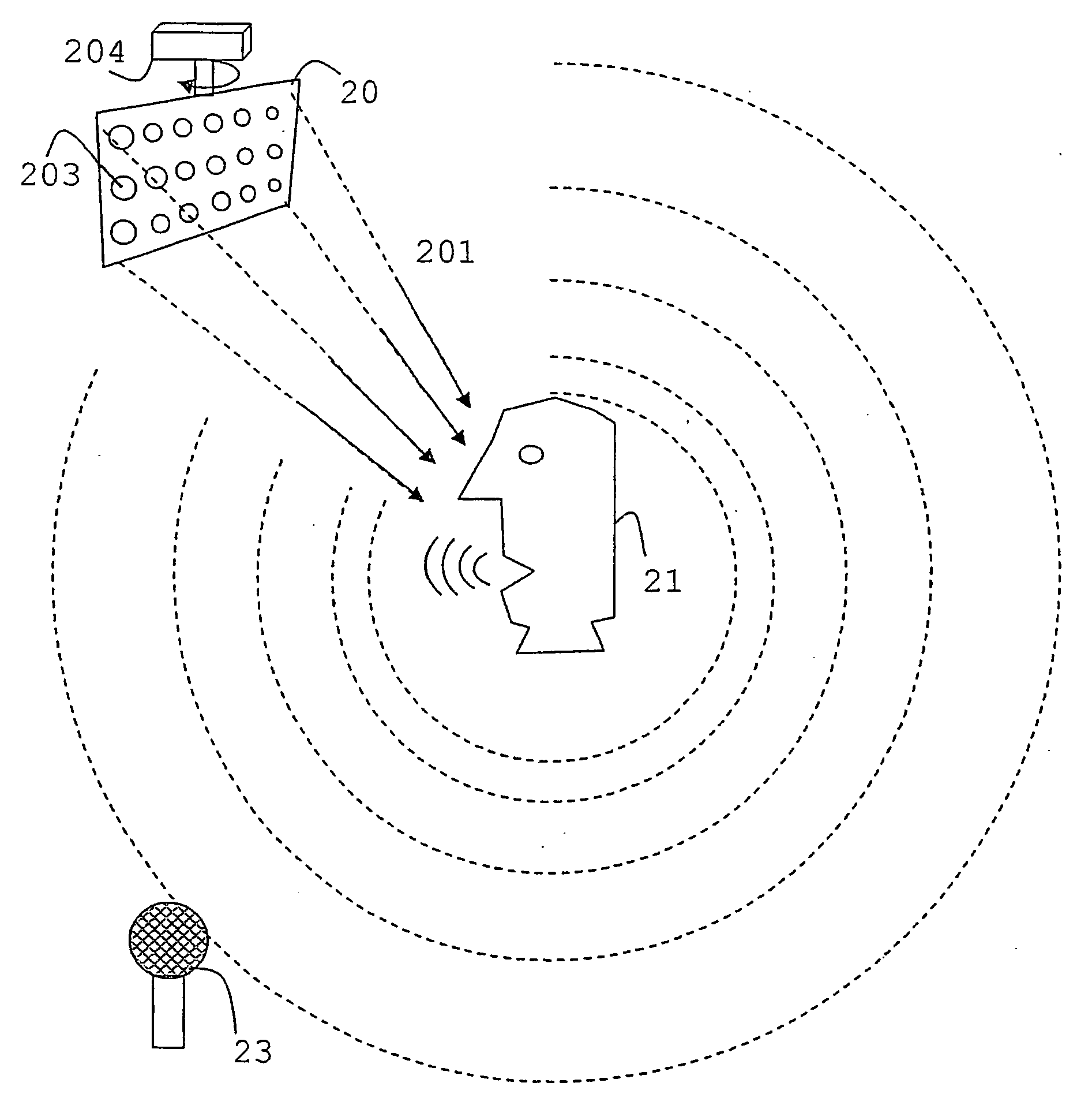
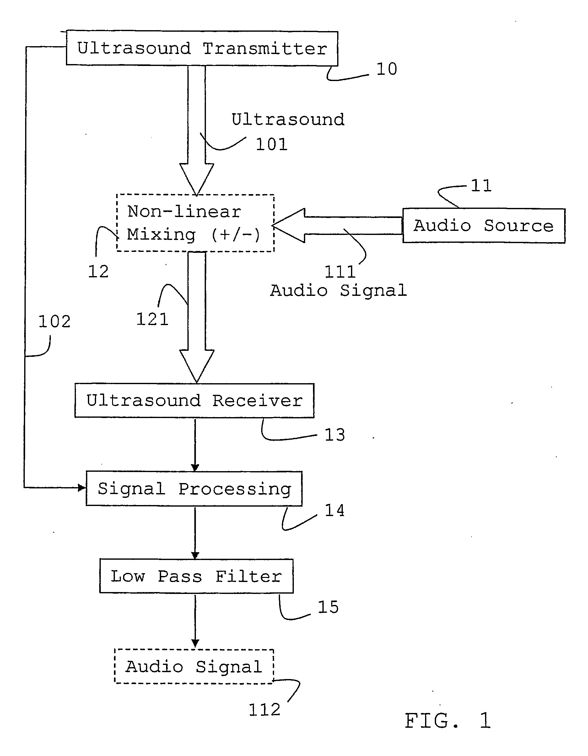
[0030]FIG. 1 is a flow diagram illustrating the operation of the directional microphone. The ultrasound transmitter 10 emits a beam of ultrasound, depicted by the double stemmed arrow 101, in the direction of the audio source 11 which may for example be a person speaking. The audible sound waves 111 emanating from the speaker's mouth interact nonlinearly in the air with the ultrasonic waves generating a source of further ultrasonic waves 121 with frequency modified by the audible signal. These generated [sum and difference] ultrasound waves radiate from the mixing point 12 and are picked up by an ultrasound receiver 13. The received signals are processed with reference to a signal 102 from the transmitter 10 using a signal processor 14 and filtered through a low-pass filter 15 to produce an audio signal 112, which is a representation of the original audio signal 111.

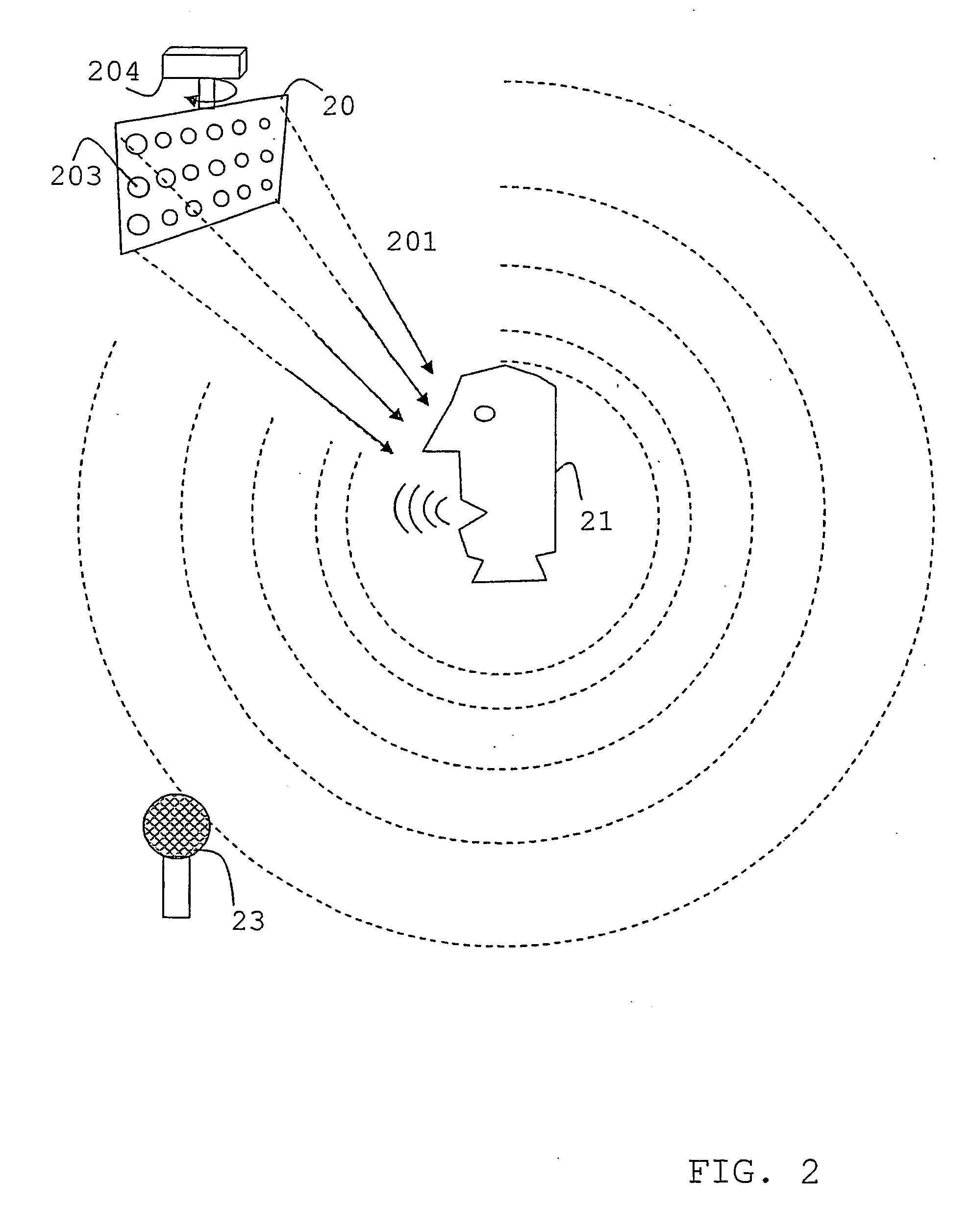
[0031]FIG. 2 is a schematic representation of a directional microphone system operating at some distance from the audi...


PUM


Abstract

A directional microphone system includes an ultrasonic emitter and receiver. The emitter directs a beam of ultrasound at the audio source with sufficient intensity that non-linear air effects cause non-linear interactions between the ultrasonic sound and the source's sonic sound. Ultrasonic frequency-mired sounds are thereby generated and these are received by the ultrasonic receiver. Signal-processing is carried out on the received signals to strip out the audio signals. The emitter and receiver may be co-located and the emitted beam may be focussed at the location of the audio source. The receiver may also be directional acid focussable. The directional microphone system may be very small and yet highly directional at sonic including low audible frequencies.

Description

[0001]The present invention relates to a microphone and a method of receiving or detecting acoustic signals, particularly to a directional microphone for portable applications and devices.BACKGROUND OF THE INVENTION[0002]Microphones, i.e. devices that convert sound-waves to electrical signals, are well known in the art. Directional forms of microphones are also known, the cardioid form being perhaps the best known, with a (wideband) directivity of 3 in theory. However, when much higher directivity is required then it is generally the case that the extent of the microphone has to be significantly greater than a wavelength of the lowest frequency where directionality is required. Thus, very directional microphones (e.g. D>>10) for low speech band frequencies, say 300 Hz, in air, tend to be large (>˜1 m in extent), and while this may be acceptable for some applications it is impractical for almost all portable applications. Thus the laws of physics dictate that highly directio...

Claims


Application Information

Patent Timeline
IPC IPC(8): H04R3/00H04R1/32H04R1/40
CPCH04R3/005
Inventor HOOLEY, ANTHONY
Owner 1 LIMITED ST JOHN S INNOVATION CENT
Why Eureka
Try Eureka