Tunnel type multi-mode microwave resonant cavity with rotation function

A microwave resonator with multiple functions, which is applied in microwave heating, electric/magnetic/electromagnetic heating, electric heating devices, etc., can solve the problems of poor radiation uniformity of microwave resonators and reduced focus of microwave energy Good uniformity of illumination, fewer microwave focusing hot spots, and uniform distribution of microwave energy

Active Publication Date: 2016-12-07
TONGJI UNIV
View PDF3 Cites 4 Cited by
  • Summary
  • Abstract
  • Description
  • Claims
  • Application Information

AI Technical Summary

Problems solved by technology

[0003] The purpose of the present invention is to overcome the disadvantage of poor radiation uniformity of the traditional cubic box-type microwave resonator, and propose a tunnel-type multi-mode microwave resonator with rotary function, which has more reflections than the traditional cuboid box-type microwave resonator On the other hand, the positions of four microwave energy feed ports were simulated and positioned by using the high-frequency structure simulation software HFSS, and four microwave tubes totaling 4KW were respectively fed into microwave energy from different directions. After electromagnetic wave energy feed simulation, the energy distribution of the microwave resonator was improved. The focus points (hot spots) of microwave energy in the resonant cavity are significantly reduced. At the same time, the middle part of the resonant cavity is designed with a pipeline installation position, which can be assembled with pipelines made of low microwave absorption materials such as ceramics and glass. The installed pipeline can be driven by the rotary device. Rotate down to make the material in the tube more evenly irradiated by microwave

Method used


Image

  • Tunnel type multi-mode microwave resonant cavity with rotation function
  • Tunnel type multi-mode microwave resonant cavity with rotation function
  • Tunnel type multi-mode microwave resonant cavity with rotation function

Examples


Embodiment

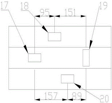
[0022] Example 1: If figure 1 As shown, the exterior of the two ends of the hexagonal main cavity 16 are fixed by two sets of four hexagonal flanges 7 fixed together by bolts. The left and right ends of the body 16 are sealed by two hexagonal end caps 9 . The four waveguides 10 installed externally can be installed with four 1KW microwave tubes, the infrared temperature probe 11 monitors the surface temperature of the ceramic tube 12, the hexagonal flange 7 and the bearing seat 6 are fixed by 6 bolts, and the bearing seat has installed bearings 1 , the bearing 1 cooperates with the left ceramic tube outer sleeve 4 and the right ceramic tube outer sleeve 13. Connected to each other, the inside is matched with the ceramic tube 12, and there is an air distribution plate 15 between the outer sleeve 13 of the ceramic tube and the exhaust pipe 14, which has the functions of air distribution and microwave leakage prevention. The outside of the left ceramic tube outer sleeve 4 coop...


PUM


Abstract

The invention relates to a tunnel type multi-mode microwave resonant cavity with a rotation function. The microwave resonant cavity consists of a hollow hexagonal prism, HFSS (High Frequency Structure Simulation Software) is used for simulating and positioning the positions of four microwave energy feedback holes, four microwave tubes with total 4KW independently feed microwave energy from different directions, the energy distribution of the microwave resonant cavity is improved through electromagnetic wave energy feedback simulation, and microwave energy focus points in the resonant cavity are obviously reduced; meanwhile, a pipeline installation position is designed on the middle position of the resonant cavity, pipelines made of low-microwave adsorption materials including ceramics and glass can be assembled; and the pipeline which finishes being installed can rotate under the driving of a rotation device, and materials in the pipeline can be subjected to even microwave radiation. In the field of environment protection, the microwave resonant cavity is suitable for processing agriculture and forestry waste materials, waste rubber, waste plastics, waste printing circuits and the like, can carry out intermittent batch processing, can be combined with other piece of conveying processing equipment to realize fluidization operation, has the advantages of simple structure and high practical application value and is favorable for industrial popularization.

Description

technical field [0001] The invention relates to a tunnel-type multi-mode microwave resonant cavity with a rotary function. Background technique [0002] Microwaves are electromagnetic waves with a frequency of 300MHz-300GHz, and the wavelength range is between 0.1cm-100cm. According to international regulations, the frequencies for civilian use are 915MHz and 2450MHz. The power of domestic microwave ovens in my country is 2450MHz. Microwave acts on polar molecular substances, and the internal molecules or atoms of the heated material vibrate at high frequency in the microwave field to generate "internal friction heat" so that the microwave energy is transferred to the molecules or atoms in the form of heat, thereby increasing the temperature of the entire material Without any heat conduction process, the inside and outside of the material can be heated and heated at the same time. The heating speed is fast, and only a fraction or a few tenths of the energy consumption of tra...

Claims


Application Information

Patent Timeline
Patent Type & Authority Applications(China)
IPC IPC(8): H05B6/64
CPCH05B6/6402H05B2206/04
Inventor 贺文智赵敏赵辰李光明朱昊辰黄菊文
Owner TONGJI UNIV
Why Eureka
Try Eureka