Exoskeleton type wounded finger rehabilitation robot

A rehabilitation robot and exoskeleton technology, applied in passive exercise equipment, physical therapy, etc., can solve the problems of inability to directly feedback the rehabilitation effect, long rehabilitation time, high labor intensity, etc., to improve the rehabilitation effect, simple and reliable tensioning mechanism , the effect of avoiding harm

Inactive Publication Date: 2016-12-14
HARBIN INST OF TECH
View PDF5 Cites 19 Cited by
  • Summary
  • Abstract
  • Description
  • Claims
  • Application Information

AI Technical Summary

Problems solved by technology

[0009] In order to solve the existing problems of high labor intensity, long rehabilitation time, and inability to provide direct f

Method used


Image

  • Exoskeleton type wounded finger rehabilitation robot
  • Exoskeleton type wounded finger rehabilitation robot
  • Exoskeleton type wounded finger rehabilitation robot

Examples


specific Embodiment approach 1

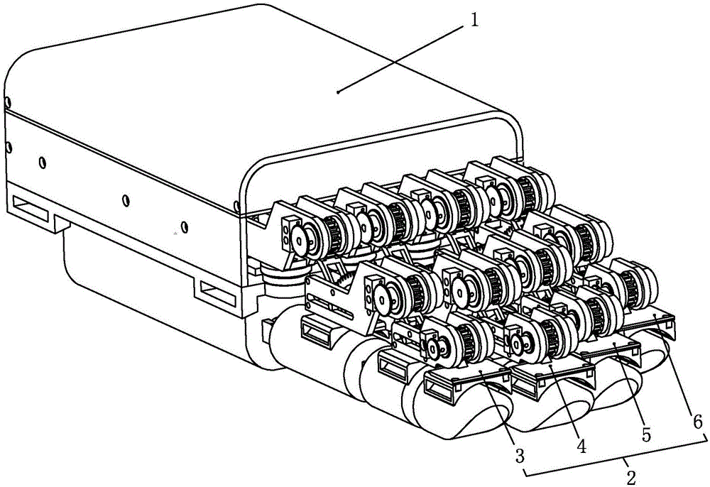
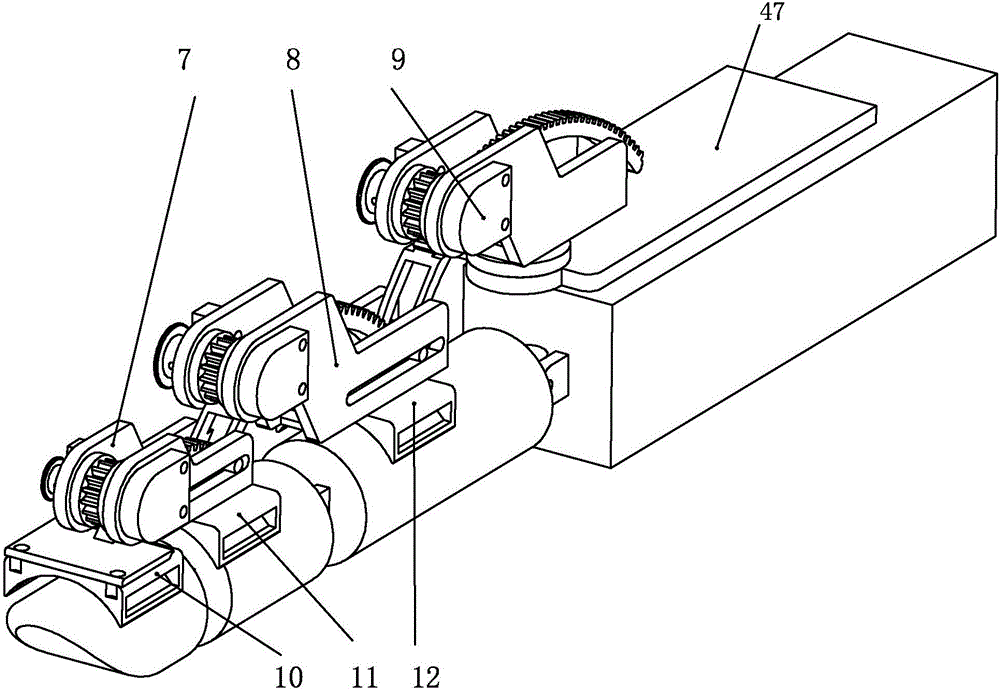
[0035] Specific implementation mode one: as Figure 1-12 As shown, the exoskeleton type trauma finger rehabilitation robot of this embodiment includes an artificial muscle drive module 1 and an exoskeleton execution module 2, and the exoskeleton execution module 2 includes an index finger exoskeleton 3, a middle finger exoskeleton 4, a ring finger exoskeleton 5 and The little finger exoskeleton 6; the index finger exoskeleton 3, the middle finger exoskeleton 4, the ring finger exoskeleton 5 and the little finger exoskeleton 6 are mainly composed of the distal interphalangeal joint unit 7, the proximal interphalangeal joint unit 8 and the metacarpophalangeal joint unit 9. The distal interphalangeal joint unit 7, the proximal interphalangeal joint unit 8, and the metacarpophalangeal joint unit 9 are respectively fixed on the corresponding first finger cuff 10, second finger cuff 11, and third finger cuff 12 by screws, and the index finger exoskeleton The metacarpophalangeal join...

specific Embodiment approach 2

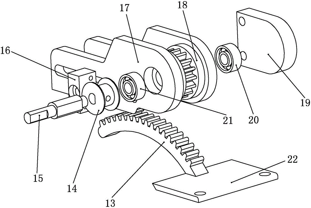
[0038] Specific implementation mode two: as figure 1 and figure 2 As shown, the distal interphalangeal joint unit 7 in this embodiment includes a first joint arc rack 13, a first joint pulley 14, a first joint shaft 15, a first joint spring baffle 16, a first joint support 17. The first joint measuring gear 18, the first joint angular displacement sensor 19 and the first connecting plate 22; one end of the first joint arc-shaped rack 13 is welded together with the first connecting plate 22, and the first connecting plate 22 is connected to the corresponding The finger cots 10 are fixedly connected, and the first joint support 17 is fixedly connected with the corresponding finger cots 11 by screws. The two side walls of the first joint support 17 are all processed with sliding grooves along its length direction, and the first joint spring baffle 16 And the first joint pulley 14 is fixed on the side wall of the first joint support 17 by screws, the first joint angular displace...

specific Embodiment approach 3

[0039] Specific implementation mode three: as figure 1 and image 3 As shown, the proximal interphalangeal joint unit 8 in this embodiment includes a second joint arc rack 23, a second joint adjustment shaft 24, a second joint pulley 28, a second joint shaft 26, and a second joint spring baffle 29. The second joint support 30, the second joint measurement gear 31, the second joint angular displacement sensor 32 and the second joint arc gear support shaft 45; the second joint support 30 is fixed on the upper end surface of the finger cot 12 by screws, the second Both side walls of the two-joint bracket 30 are processed with sliding grooves along its length direction, and one end of the second joint arc rack 23 is installed on the sliding groove of the first joint bracket 17 by the second joint adjustment shaft 24, and the second The joint arc gear support shaft 45 is installed on the second joint support 30, the second joint arc rack 23 is supported on the second joint arc gea...


PUM


Abstract

The invention relates to a finger rehabilitation robot, in particular to an exoskeleton type wounded finger rehabilitation robot. The exoskeleton type wounded finger rehabilitation robot can solve the problems that an existing exoskeleton type wounded finger rehabilitation robot is large in labor intensity and long in rehabilitation time and cannot directly feed a rehabilitation effect back. A metacarpophalangeal joint unit of an index finger exoskeleton is fixed to a first spur gear at the front end of a drive module through a screw; a metacarpophalangeal joint unit of a middle finger exoskeleton is fixed to a second spur gear at the front end of the drive module through a screw; a metacarpophalangeal joint unit of a ring finger exoskeleton is fixed to a third spur gear at the front end of the drive module through a screw; a metacarpophalangeal joint unit of a little finger exoskeleton is fixed to a fourth spur gear at the front end of the drive module through a screw, three steel wires are respectively led out of a pulley block of an artificial muscle drive module, and the led-out ends of the three steel wires are sequentially connected with the a first pulley of a distal interphalangeal joint unit, a second pulley of a proximal interphalangeal joint unit and a third pulley of the metacarpophalangeal joint unit. The exoskeleton type wounded finger rehabilitation robot is applied to exoskeleton type wounded finger rehabilitation.

Description

technical field [0001] The invention relates to a rehabilitation robot, in particular to an exoskeleton-type trauma finger rehabilitation robot, which belongs to the field of biomechanical engineering. Background technique [0002] As a new type of auxiliary rehabilitation equipment to help patients with finger trauma to quickly restore motor function, hand exoskeleton rehabilitation manipulator has become a research hotspot in the field of biomechanical engineering. [0003] The exoskeleton rehabilitation manipulator is mainly composed of the driving device and the exoskeleton mechanism of the manipulator. The driving device is the power source of the rehabilitation manipulator. Its requirement is to make the movement of the driving finger joints fully simulate the movement of human fingers in the natural state as much as possible. On the premise of avoiding additional damage to the traumatized finger, the patient can recover the motor function of the finger as soon as poss...

Claims


Application Information

Patent Timeline
IPC IPC(8): A61H1/02
CPCA61H1/0288A61H2201/1207A61H2201/14A61H2201/1638A61H2201/165A61H2205/067
Inventor 付宜利张福海牟洋杨磊刘洪山王鹏
Owner HARBIN INST OF TECH
Why Eureka
Try Eureka