Piston rod sleeve snap spring processing equipment and method

A technology for processing equipment and piston rods, applied in the processing equipment and processing fields of piston rod sleeve circlips, can solve the problems of poor quality and low efficiency of manual installation, and achieve the effects of improving production efficiency and quality, saving operating costs and saving labor.

Active Publication Date: 2016-12-14
ANHUI LAITE GAS SPRING CO LTD
View PDF6 Cites 4 Cited by
  • Summary
  • Abstract
  • Description
  • Claims
  • Application Information

AI Technical Summary

Problems solved by technology

[0005] Aiming at the problems of low manual installation efficiency and poor quality of piston rod circlips in the prior art, the present invention provides a processing equipment and processing method for piston rod sleeve circlips

Method used


Image

  • Piston rod sleeve snap spring processing equipment and method

Examples


Embodiment 1

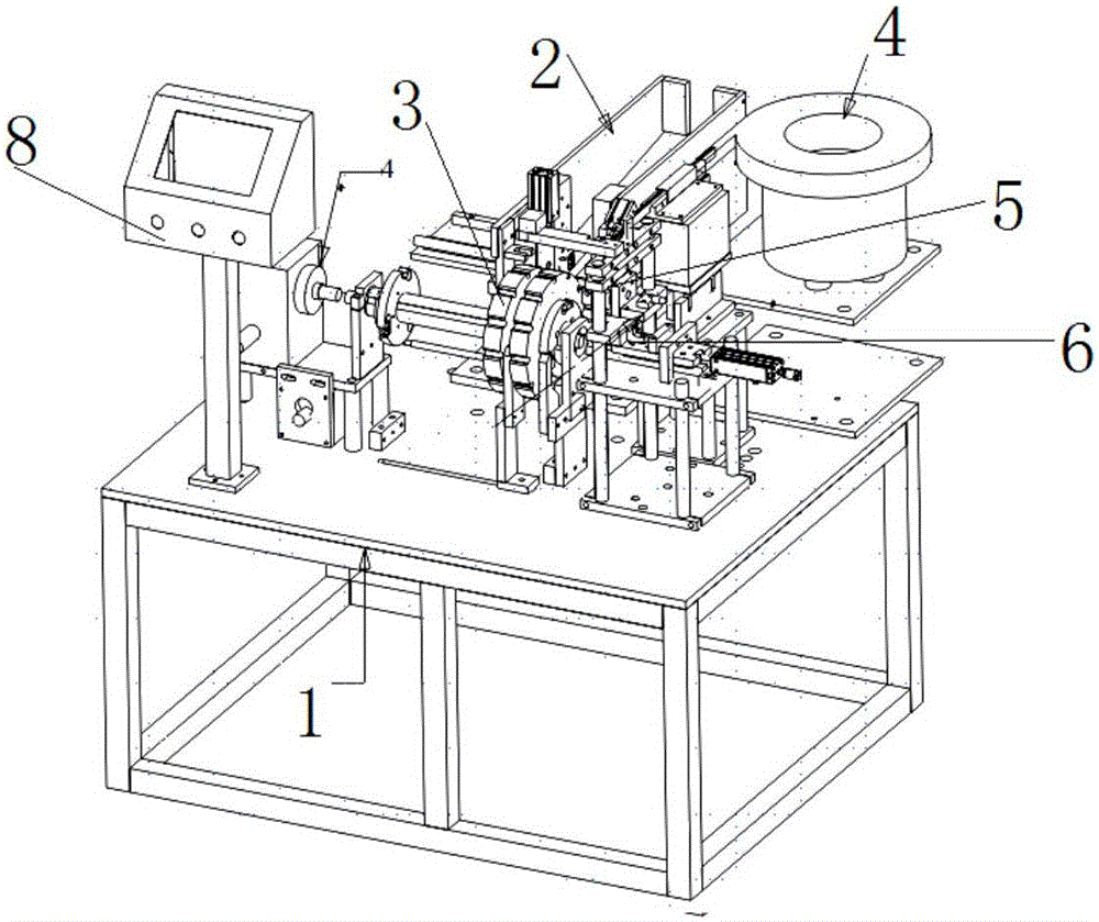
[0042] combine figure 1, a piston rod sleeve circlip processing equipment, including a frame 1, and also includes a piston rod automatic feeding mechanism 2, a piston rod automatic sorting and placement mechanism 3, a snap ring automatic feeding mechanism 4, and a snap ring automatic grasping and placement Mechanism 5, piston rod snap ring automatic assembly mechanism 6, product output mechanism 7 and electrical control system 8, piston rod automatic feeding mechanism 2 sends the piston rod to piston rod automatic sorting and placement mechanism 3, snap ring automatic feeding mechanism 4 Send the snap ring to the snap ring automatic grabbing and placement mechanism 5, the snap ring automatic grabbing and placement mechanism 5 will transport the snap ring to the piston rod snap ring automatic assembly mechanism 6, and the piston rod automatic sorting and placement mechanism 3 will The piston rod is transported to the piston rod snap ring automatic assembly mechanism 6, the pist...

Embodiment 2

[0044] A kind of piston rod sleeve circlip processing equipment of this embodiment is similar to Embodiment 1, the difference is that the piston rod automatic feeding mechanism 2 includes a chute, and the piston rod automatic sorting and placement mechanism 3 includes a rotating wheel, which rotates The roulette is uniformly provided with grooves matched with the piston rod, and the rotating roulette faces the chute, and the rotation is controlled by the electric control system 8 .

[0045] Piston rod enters in the chute of piston rod automatic feeding mechanism 2, and the rotating roulette rotates, and the piston rod in the chute enters automatically on the groove of rotating roulette.

Embodiment 3

[0047] A kind of processing equipment for piston rod sleeve and circlip of this embodiment is similar to that of Embodiment 1, the difference is that the snap ring automatic feeding mechanism 4 includes a vibrating plate, a slide rail and a straight track, and the inner surface of the vibrating plate is provided with a slide rail , the slide rail is connected with the straight rail.

[0048] The snap ring is placed in the vibrating plate, and the vibrating plate rotates. The snap ring moves along the slide rail on the inner side of the vibrating plate, and is placed on the straight track in sequence, moving forward continuously.


PUM


Abstract

The invention discloses a piston rod sleeve snap spring processing equipment and method, belonging to the technical field of piston rod assembly. The equipment comprises a rack, a piston rod automatic feeding mechanism, a piston rod automatic sequencing and putting mechanism, a snap ring automatic feeding mechanism, a snap ring automatic grabbing and putting mechanism, a piston rod and snap ring automatic assembly mechanism, a product discharging mechanism and an electrical control system, wherein the piston rod automatic feeding mechanism feeds piston rods to the piston rod automatic sequencing and putting mechanism; the snap ring automatic feeding mechanism feeds snap rings to the snap ring automatic grabbing and putting mechanism; the snap ring automatic grabbing and putting mechanism conveys the snap rings to the piston rod and snap ring automatic assembly mechanism; the piston rod automatic sequencing and putting mechanism conveys the piston rods to the piston rod and snap ring automatic assembly mechanism; the piston rod and snap ring automatic assembly mechanism assemblies the snap rings and the piston rods; and the product discharging mechanism conveys out the assembled piston rods sleeved with the snap rings. The equipment and the method have the effects of improving the production efficiency and ensuring the product quality after installation.

Description

technical field [0001] The invention relates to the technical field of piston rod assembly, in particular to a processing equipment and a processing method for a ring spring of a piston rod sleeve. Background technique [0002] Before this equipment was not developed, the piston rod circlip assembly was done manually. The assembly of products is greatly affected by the proficiency of personnel and the external environment. The installation efficiency of a new employee is about 600 per hour, and that of a skilled employee is only about 1,000 per hour. If the temperature is low in winter, the efficiency will be even lower; sometimes when an employee installs the circlip, it is easy to damage the lever and affect the quality . [0003] Chinese utility model / invention patent, authorized announcement number CN 102248515 B, authorized announcement date 2013.06.12, discloses a device for automatically installing circlips, which consists of a frame, a vertical cylinder, a pressure...

Claims


Application Information

Patent Timeline
Patent Type & Authority Applications(China)
IPC IPC(8): B23P19/04
CPCB23P19/001B23P19/007B23P19/048
Inventor 陶声荣
Owner ANHUI LAITE GAS SPRING CO LTD
Why Eureka
Try Eureka