
Scrap iron collection equipment in metal machining cooling liquid

A technology for metal processing and collection equipment, applied in metal processing equipment, metal processing machinery parts, manufacturing tools, etc., can solve problems such as troubles, achieve the effects of reducing environmental pollution, convenient operation, and saving resources

Inactive Publication Date: 2016-12-14
天津睿兴科技有限公司
View PDF0 Cites 9 Cited by
  • Summary
  • Abstract
  • Description
  • Claims
  • Application Information

AI Technical Summary

Problems solved by technology

In order to make the cutting process more efficient and smooth, it is necessary to use a large amount of machining coolant. The coolant will be mixed with the iron filings generated during machining. Traditional devices generally collect the coolant and iron filings directly in containers. Workers need to It is troublesome to replace or clean the filter frequently

Method used


Image

  • Scrap iron collection equipment in metal machining cooling liquid

Examples


Embodiment Construction

[0023] It should be noted that, in the case of no conflict, the embodiments of the present invention and the features in the embodiments can be combined with each other.

[0024] In describing the present invention, it should be understood that the terms "center", "longitudinal", "transverse", "upper", "lower", "front", "rear", "left", "right", " The orientations or positional relationships indicated by "vertical", "horizontal", "top", "bottom", "inner" and "outer" are based on the orientations or positional relationships shown in the drawings, and are only for the convenience of describing the present invention and Simplified descriptions, rather than indicating or implying that the device or element referred to must have a particular orientation, be constructed and operate in a particular orientation, and thus should not be construed as limiting the invention. In addition, the terms "first", "second", etc. are used for descriptive purposes only, and should not be understood ...


PUM


Abstract

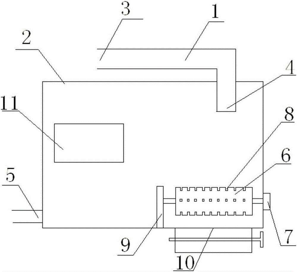
The invention provides scrap iron collection equipment in metal machining cooling liquid. The scrap iron collection equipment comprises a flow guide groove, a liquid storage groove, an electromagnetic rotary roller, a motor, a controller and a displayer. The inlet end of the flow guide groove is connected with a lathe, and the outlet end of the flow guide groove communicates with the liquid storage groove; a liquid outlet is formed in the bottom of the liquid storage groove and connected with a cooling liquid guide pipe of the lathe; the electromagnetic rotary roller is arranged in the liquid storage groove; the motor is arranged outside the liquid storage groove; one end of the electromagnetic rotary roller penetrates through the side wall of the liquid storage groove and is rotatably connected with the motor; the one, away from the motor, of the electromagnetic rotary roller is connected with a support arranged in the liquid storage groove; a plurality of grooves are formed in the surface of the electromagnetic rotary roller along the axis; the controller is connected with the motor and the displayer; and the controller and the displayer are arranged on the outer surface of the liquid storage groove. According to the scrap iron collection equipment in the metal machining cooling liquid, scrap iron in the cooling liquid can be automatically collected and adsorbed, so that the cooling liquid can be recycled.

Description

technical field [0001] The invention belongs to the field of iron filings collection equipment, in particular to an iron filings collection equipment in metal processing cooling liquid. Background technique [0002] In the machinery manufacturing industry, there is a common problem, that is, iron filings from metal processing and cutting often injure human feet, which seriously affects the personal safety of the staff. Iron filings are scattered on the workshop floor, affecting the normal processing of the workshop. . Nowadays, metal processing in machining workshops produces a large amount of metal iron filings every day. These iron filings often fail to attract people's attention, but are scattered on a certain corner of the workshop floor. At present, traditional tools such as brooms and lamps are generally used for manual cleaning, which is not only inefficient, but also unsatisfactory. Iron filings on some dead corners are still not cleaned well, and potential safety h...

Claims


Application Information

Patent Timeline
Patent Type & Authority Applications(China)
IPC IPC(8): B23Q11/00B23Q11/10
CPCB23Q11/0064B23Q11/1069Y02P70/10
Inventor 江曼曼
Owner 天津睿兴科技有限公司
Learn More