Unmanned aerial vehicle arm latching component and unmanned aerial vehicle

A technology for locking components and drones, applied to aircraft parts, affecting the air flow flowing through the aircraft surface, and the fuselage, etc., can solve the problems of large connecting structural parts, affecting dynamic stability, and portability restrictions, and achieve deformation torque The effect of large size, high locking stability and small force

Inactive Publication Date: 2016-12-14
厦门乔昇科技有限公司
View PDF9 Cites 2 Cited by
  • Summary
  • Abstract
  • Description
  • Claims
  • Application Information

AI Technical Summary

Problems solved by technology

But it is very limited in terms of portability
Some design schemes adopt the detachable method of the machine arm, but in order to ensure the stability of the machine arm, this kind of method is usually complicated to operate and requires additional fastening, which is inconvenient when installing and disassembling.
Very few design schemes use folding arms, or the arms cannot be stabilized due to the stability of the connection structure, and there will be a large shake during use, which will affect the stability of the power; or in order to ensure the stability of the connection structure. Too many fastening screws affect the convenience of deployment
[0003] The main problems at present are: 1. The material of the locking structure, although the existing aluminum alloy or even titanium alloy material is very high in hardness, but because the position of the connecting shaft is very small, the moment encountered by the connecting point in the use of large drones It is very large and can only be ensured by increasing the size of the connecting body to ensure its strength and stability, which leads to too large connecting structural parts; 2. The locking method of the locking structural parts ensures easy deployment and easy locking while ensuring To ensure the firmness after locking, it is difficult to achieve both in the current mainstream locking methods.

Method used


Image

  • Unmanned aerial vehicle arm latching component and unmanned aerial vehicle
  • Unmanned aerial vehicle arm latching component and unmanned aerial vehicle
  • Unmanned aerial vehicle arm latching component and unmanned aerial vehicle

Examples


Embodiment Construction

[0023] Embodiments of the present invention are described in detail below, examples of which are shown in the drawings, wherein the same or similar reference numerals designate the same or similar elements or elements having the same or similar functions throughout. The embodiments described below by referring to the figures are exemplary and are intended to explain the present invention and should not be construed as limiting the present invention.

[0024] The arm locking component for an unmanned aerial vehicle according to an embodiment of the present invention will be described in detail below with reference to the accompanying drawings.

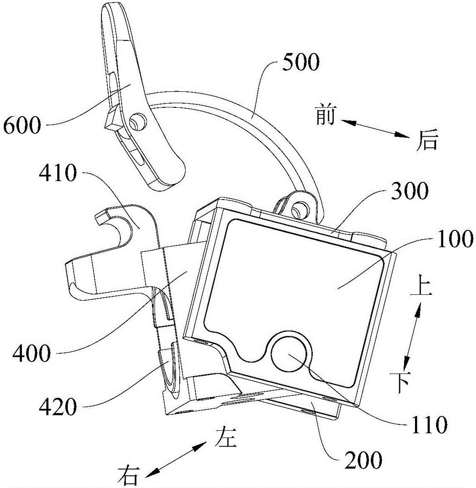
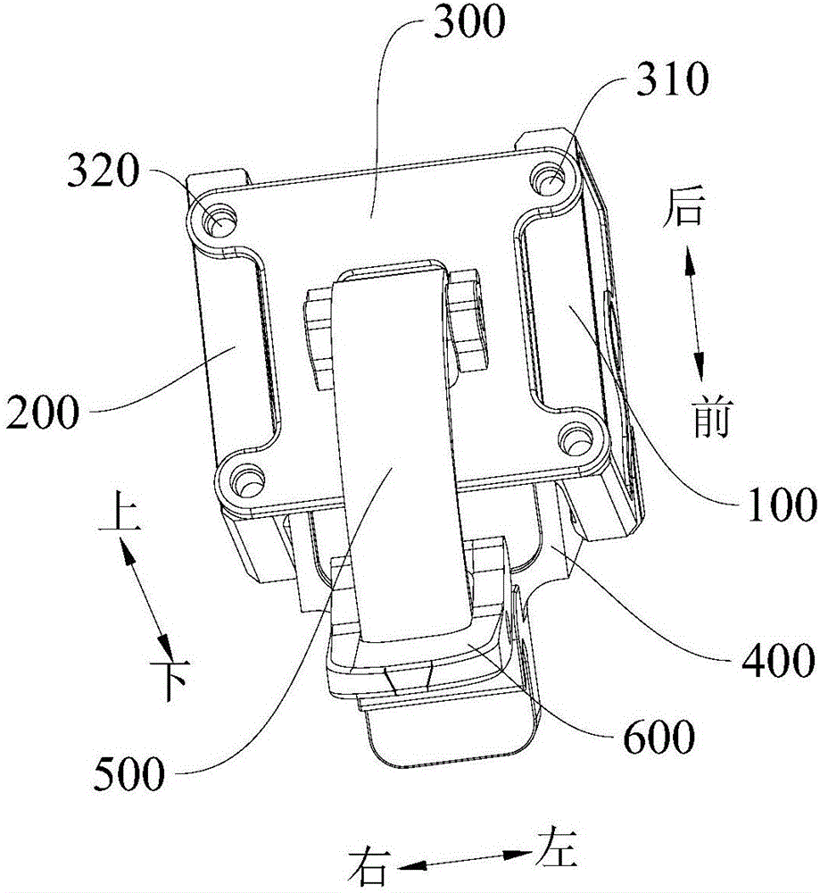
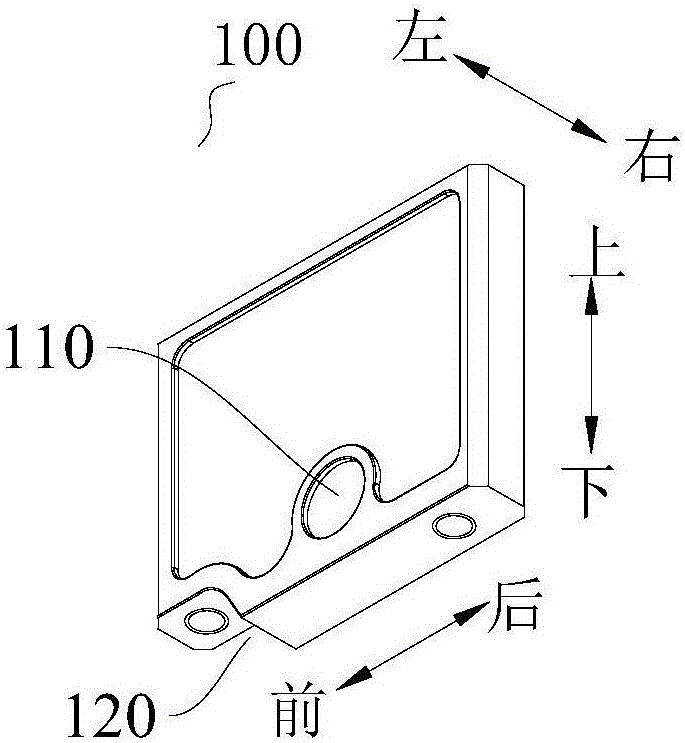
[0025] Such as Figure 1 to Figure 4 As shown, the arm locking component for a drone according to the embodiment of the present invention includes: a left base plate 100 , a right base plate 200 , an upper base plate 300 , an arm connecting block 400 , a connecting bar 500 , and a pin 600 .

[0026] Specifically, the left base plate 10...


PUM


Abstract

The invention provides an unmanned aerial vehicle arm latching component and an unmanned aerial vehicle. The unmanned aerial vehicle arm latching component comprises a left substrate, a right substrate, an upper substrate, a vehicle arm connecting block, a connecting strip and a pin sheet, wherein the left substrate and the right substrate are arranged in bilateral symmetry at an interval; the upper substrate is arranged above the left substrate and the right substrate and is detachably connected with the left substrate and the right substrate; the vehicle arm connecting block is arranged between the left substrate and the right substrate and is positioned below the upper substrate; the vehicle arm connecting block is pivotably connected with the left substrate and the right substrate; a clamping hook and a vehicle arm connecting hole positioned below the clamping hook are formed on the vehicle arm connecting block; one end of the connecting strip is pivotably connected with the upper substrate; the pin sheet is pivotably connected with the other end of the connecting strip. The unmanned aerial vehicle arm latching component provided by the embodiment of the invention is high in latching stability.

Description

technical field [0001] The invention relates to the technical field of drones, in particular to an arm locking component for a drone and a drone with the arm locking component for a drone. Background technique [0002] In the use of large industrial drones, due to the stability requirements of the mechanical structure, most of them are manufactured with fixed arms. But it is very limited in terms of portability. Some design schemes adopt the detachable method of the arm, but in order to ensure the stability of the arm, this method is usually complicated to operate and requires additional fastening, which is inconvenient during installation and disassembly. Very few design schemes use folding arms, or the arms cannot be stabilized due to the stability of the connection structure, and there will be a large shake during use, which will affect the stability of the power; or in order to ensure the stability of the connection structure. Too many fastening screws affect the conve...

Claims


Application Information

Patent Timeline
Patent Type & Authority Applications(China)
IPC IPC(8): B64C1/30B64C39/00
CPCB64C1/30B64C39/00
Inventor 许燕中陈杰
Owner 厦门乔昇科技有限公司
Why Eureka
Try Eureka