

Gas monitoring and warning protection mechanism
A technology for monitoring alarms and protection mechanisms, applied in the directions of alarms, mechanical equipment, engine components, etc., can solve problems such as gas leakage and inconvenience, and achieve the effect of avoiding continued leakage
- Summary
- Abstract
- Description
- Claims
- Application Information
AI Technical Summary
Problems solved by technology
Method used
Image

Examples
Embodiment Construction
[0029] The following specific embodiments will be further described in conjunction with the above-mentioned drawings.
[0030] In the following, numerous specific details are set forth in order to provide a thorough understanding of the concepts underlying the described embodiments. It will be apparent, however, to one skilled in the art that the described embodiments may be practiced without some or all of these specific details. In other instances, well known processing steps have not been described in detail.
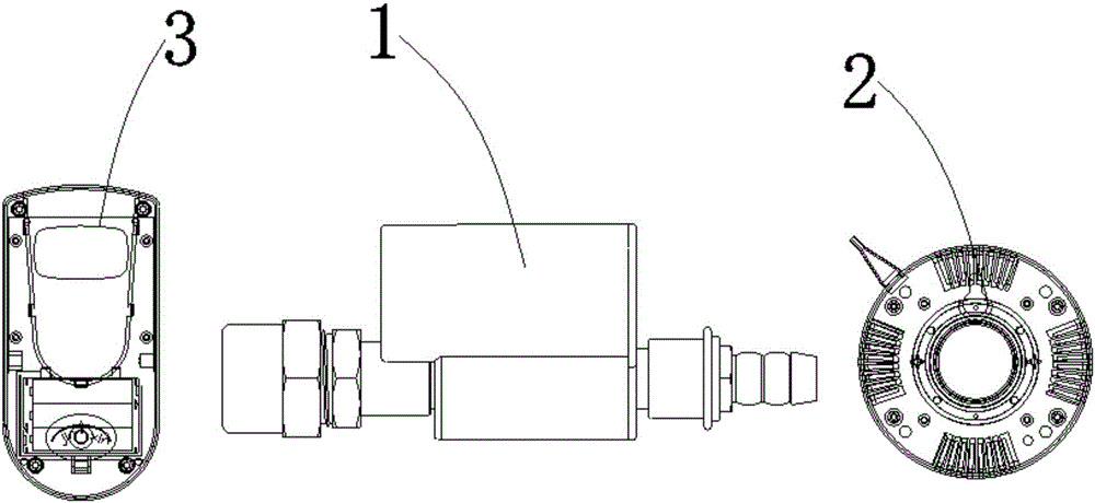
[0031] like figure 1 As shown, a gas monitoring and alarm protection mechanism includes: a solenoid valve 1 , a detection alarm 2 and a remote controller 3 . The remote control 3 controls the opening and closing of the electromagnetic valve 1, and the detection alarm 2 detects whether the electromagnetic valve 3 is leaking. Therefore, the gas monitoring and alarm protection mechanism can control the opening and closing of the solenoid valve 1 through the remote co...
PUM
 Abstract
Description
Claims
Application Information