Dampening device

A shock absorber, foam technology, applied in the direction of charging system, machine/engine, pipe components, etc., can solve the problem of being too bulky and insufficient to suppress pressure pulsation, and achieve the effect of suppressing pressure pulsation

Inactive Publication Date: 2016-12-14
AKWEL SA
View PDF6 Cites 3 Cited by
  • Summary
  • Abstract
  • Description
  • Claims
  • Application Information

AI Technical Summary

Problems solved by technology

[0004] However, in a large number of applications the state of the art shock absorbers are insufficient to suppress pressure pulsations (rubber tubing) and / or are too bulky and / or create limitations for mass implantation (e.g. shock absorbers with anti-air valves )

Method used


Image

  • Dampening device
  • Dampening device
  • Dampening device

Examples


Embodiment Construction

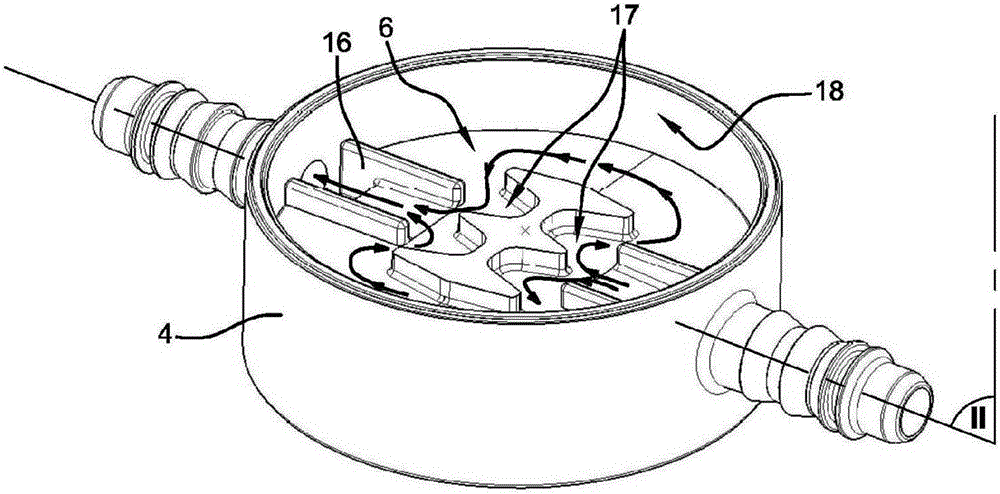
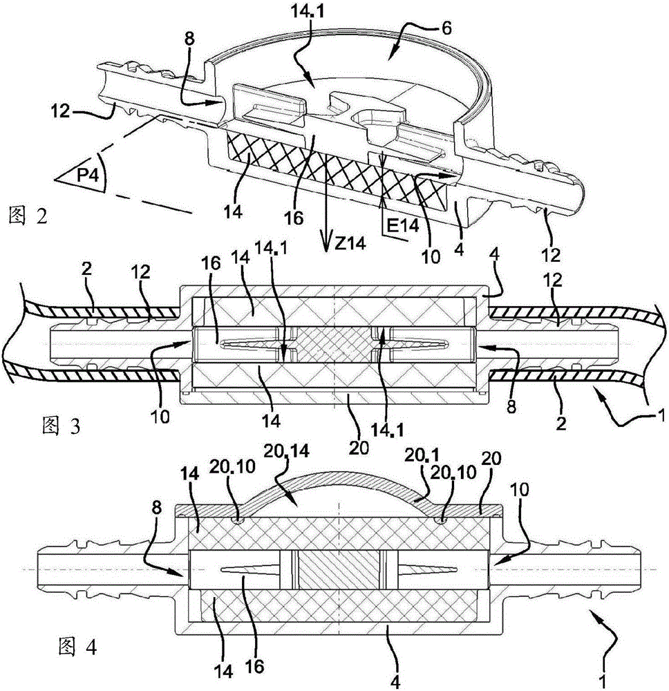
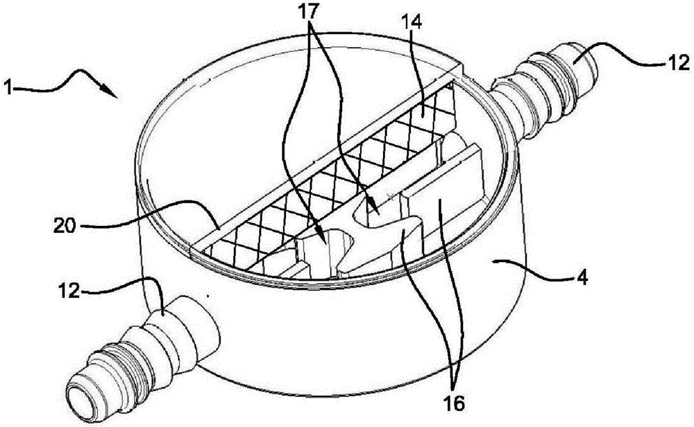
[0109] figure 1 , figure 2 and image 3 The damping device 1 is shown according to a first embodiment. The shock absorbing device 1 has the function of suppressing pressure pulsation, which can propagate in the fluid pipeline 2, in this case, the fluid pipeline includes the gas oil fuel pipeline of the motor vehicle.

[0110] The shock absorber 1 includes a body 4 . The body 4 defines a chamber 6 and two holes 8 and 10 serving as inlet and outlet for fluid in the chamber 6 . exist Figures 1 to 3 In the example shown, the body 4 includes two nozzles 12 configured to connect the fluid conduit 2 to the body 4 .

[0111] The shock absorbing device also includes i) two shock absorbing members 14 and ii) a clamping member 16 . In particular, each shock absorbing member 14 has a function of suppressing pressure pulsation when the shock absorbing device 1 operates. Here, the shock absorbing members 14 are arranged such that fluid flows between the shock absorbing members 14 w...


PUM


Abstract

This dampening device comprises a body defining a chamber and presenting at least one orifice intended for the inlet and the outlet of the fluid in the chamber. The dampening device further comprises i) a dampening member located in the chamber and comprising at least one foam with closed cells, and ii) a holding member configured to hold the dampening member in place. The dampening device being characterized in that at least one foam has a porosity comprised between 50% and 98%.

Description

technical field [0001] The invention relates to a damping device for damping pressure pulsations that can propagate in a fluid line, such as a fuel line of a motor vehicle. Background technique [0002] The invention is applicable to the field of fluid pipelines where pressure pulsation or peak may occur. In particular, the invention finds application in the field of fluid conduits for motor vehicles, in particular utility vehicles, passenger vehicles and heavy goods vehicles. More particularly, the invention is applicable to the field of fuel lines, not only fuel supply lines but also fuel return lines. [0003] In the state of the art there is a shock absorbing device comprising a duct consisting of an elastically deformable material such as rubber. During pressure pulsations, the pipe made of rubber deforms, thereby partially suppressing the pressure pulsations. Furthermore, there is a shock absorbing device comprising a body delimiting a chamber and presenting two hol...

Claims


Application Information

Patent Timeline
Patent Type & Authority Applications(China)
IPC IPC(8): F16L55/05F16L55/053F02M37/00
CPCF16L55/04F02M37/0041F16L55/0279F16L55/0332F16L55/0336F16L55/05F16L55/053
Inventor 马克·诺弗拉尼彼得·福尔斯特罗皮埃尔·劳伦
Owner AKWEL SA
Why Eureka
Try Eureka