
Induction camera support

A camera and sensor technology, applied in the field of electronic accessories, can solve the problems of no protective device, fixed structure, single function, etc., and achieve the effect of convenient operation and simple structure

Inactive Publication Date: 2016-12-14
CHANGZHOU XINRUI AUTO PARTS MFG
View PDF0 Cites 0 Cited by
  • Summary
  • Abstract
  • Description
  • Claims
  • Application Information

AI Technical Summary

Problems solved by technology

The existing camera bracket structure is fixed, the function is single, there is no supporting protective device, and the camera cannot be protected

Method used


Image

  • Induction camera support

Examples


Embodiment Construction

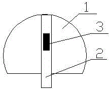
[0009] Such as figure 1 It is a schematic diagram of the structure of the present invention, an induction camera bracket, including a mounting shell 1 and a telescopic rod 2, the inner center of the mounting shell 1 is provided with a telescopic rod 2, and the telescopic rod 2 is provided with a sensor 3, and the camera is stretched through the sensor Adjustable to suit different usage needs.

[0010] The above description is only illustrative, rather than restrictive, to the present invention. Those skilled in the art understand that many modifications, changes or the like can be made without departing from the spirit and scope defined by the appended claims. effect, but all will fall within the protection scope of the present invention.


PUM


Abstract

The invention relates to the technical field of electronic accessories, in particular to an induction camera support. An existing camera support is fixed in structure, simplex in function, free of a matched protection device and not capable of protecting a camera. The induction camera support comprises an installation shell and a telescopic rod. The telescopic rod is arranged at the center of the interior of the installation shell. An inductor is arranged in the telescopic rod. The induction camera support is simple in structure and convenient to operate; and stretch-out and draw-back regulation is conducted on the camera through the inductor so that the induction camera support can adapt to different use requirements.

Description

technical field [0001] The invention relates to the technical field of electronic accessories, in particular to an induction camera bracket. Background technique [0002] The camera bracket is a part used to fix the camera. Depending on the application environment, the shape of the bracket is also different. The camera bracket is generally a small bracket, and there are two types of injection molding type and metal type. It can directly fix the camera or pass through the protective cover. Fix the camera, all camera brackets have universal adjustment function, through the adjustment of the bracket, the lens of the camera can be accurately directed to the scene to be photographed. The existing camera support structure is fixed, the function is single, there is no matching protective device, and the camera cannot be protected. Contents of the invention [0003] In order to overcome the existing above-mentioned shortcomings, the present invention provides an induction camera ...

Claims


Application Information

Patent Timeline
Patent Type & Authority Applications(China)
IPC IPC(8): F16M11/26
CPCF16M11/26F16M2200/00
Inventor 杜向峰
Owner CHANGZHOU XINRUI AUTO PARTS MFG
Learn More