Supercharge Your Innovation With Domain-Expert AI Agents!

Output shaft torque detection system and working method thereof

A detection system and working method technology, applied in the direction of force/torque/power measuring instrument, measuring device, instrument, etc., can solve the problems such as poor accuracy of shaking the dial, low production efficiency, easy fatigue of operators, etc., and achieve rapid response , Improve production efficiency and save labor costs

Active Publication Date: 2016-12-14
JIANGSU LEILI MOTOR
View PDF7 Cites 0 Cited by
  • Summary
  • Abstract
  • Description
  • Claims
  • Application Information

AI Technical Summary

Problems solved by technology

The operator is prone to fatigue in this test method, and the production efficiency is low, and the accuracy of the shaking dial is poor.

Method used


Image

  • Output shaft torque detection system and working method thereof
  • Output shaft torque detection system and working method thereof
  • Output shaft torque detection system and working method thereof

Examples


Embodiment 1

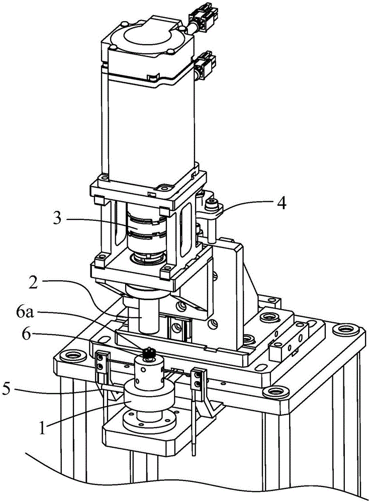
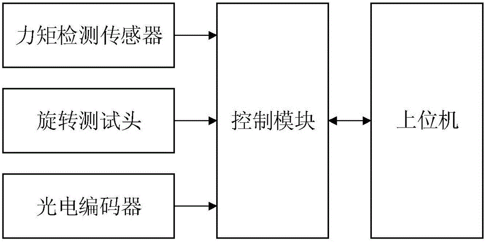
[0038] Such as figure 1 and figure 2 As shown, this embodiment 1 provides an output shaft torque detection system, including: a host computer, a control module, and a detection station for placing shaft components; the control module is suitable for obtaining the detection station The corresponding detection data is sent to the host computer to classify the shaft parts.

[0039] Among them, the control module is, for example but not limited to, Mitsubishi, Siemens PLC modules, and industrial computers with built-in embedded systems. The upper computer is for example but not limited to a PC and an industrial computer.

[0040] A torque detection sensor 1 is provided below the detection station, and a rotary test head 2 is provided above; the control module is suitable for driving the rotary test head down by detecting the lifting cylinder, so as to mesh with the gear end of the shaft component, And control the rotating test head to drive the gear 6a of the shaft part 6 to r...

Embodiment 2

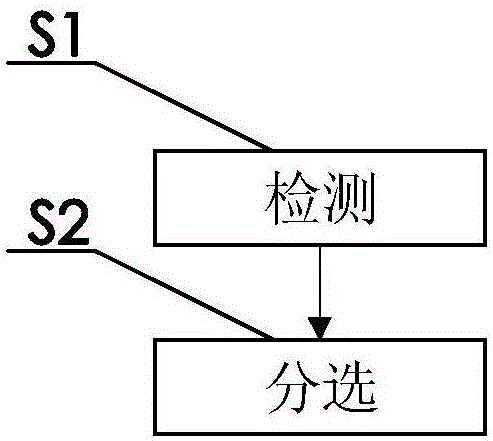
[0049] Such as image 3 and Figure 4 As shown, on the basis of embodiment 1, this embodiment 2 also provides a working method of the output shaft torque detection system, including the following steps:

[0050] Step S1, detection; and

[0051] Step S2, sorting.

[0052] The output shaft torque detection system is as described in Embodiment 1, and will not be repeated here.

[0053] Specifically, the method detected in the step S1 includes:

[0054] Step S11, starting torque detection, and

[0055] Step S12, friction torque detection.

[0056] Set the sorting range values ​​corresponding to the initial torque and friction torque data through the host computer. Specifically, the sorting range value corresponding to the initial torque is for example Figure 4 In the range of 5-5.5, the sorting range value corresponding to the friction torque is for example Figure 4 In the range of 4.5-6.

[0057] The method for detecting the initial torque in step S11 includes: the con...


PUM


Abstract

The invention relates to an output shaft torque detection system and a working method thereof. The output shaft torque detection system comprises an upper computer, a control module and a detection station used for containing shaft parts; the control module is used for sending obtained corresponding detection data of the detection station to the upper computer to classify the shaft parts. According to the output shaft torque detection system and the working method thereof, the rotating torque for driving shaft rotation in the output shaft parts are detected, and the output shaft parts are classified according to detected rotation torque values, so that customers can select and use the output shaft parts with different input rotation torques; integration and intelligentization of detection are achieved, the testing precision is high, and a quick response can be achieved; compared with original manual detection, the labor cost is saved, the production efficiency is improved, and efficient and lean production can be achieved.

Description

technical field [0001] The invention relates to a shaft detection device, in particular to an output shaft torque detection system and a working method thereof. Background technique [0002] The output shaft torque detection of the original shaft components uses a shaking dial, a single station is manually shaken, and the human eye recognizes and judges the marked area pointed by the pointer, and indirectly judges whether the product is qualified or not. The random inspection method is to manually use the torque gauge to twist the part, and human eyes can recognize and judge the marked area pointed by the pointer, and indirectly judge whether the product is qualified or not. Operators in this test method are prone to fatigue, and the production efficiency is low, and the accuracy of the shake dial is poor. Contents of the invention [0003] The purpose of the present invention is to provide an output shaft torque detection system and its working method, so as to realize t...

Claims


Application Information

Patent Timeline
IPC IPC(8): G01L5/00
CPCG01L5/00
Inventor 谈金锋周志光陆游李登奇
Owner JIANGSU LEILI MOTOR
Features
  • R&D
  • Intellectual Property
  • Life Sciences
  • Materials
  • Tech Scout
  • Unparalleled Data Quality
  • Higher Quality Content
  • 60% Fewer Hallucinations
Learn More