A tool positioning method suitable for side milling of non-developable ruled surfaces

A technology of tool positioning and texture, which is applied in general control systems, program control, instruments, etc., can solve the problems of large calculation time, principle error, and large error, and achieve the effect of improving processing efficiency and reducing processing errors

Active Publication Date: 2019-01-04
TSINGHUA UNIV
View PDF4 Cites 0 Cited by
  • Summary
  • Abstract
  • Description
  • Claims
  • Application Information

AI Technical Summary

Problems solved by technology

[0002] Currently, if figure 1 As shown, the non-developable ruled surface is different from the developable ruled surface. The magnitude and direction of the normal vectors of each point on the same straight generatrix of the surface are different, and there are twist angles (such as figure 2 As shown), due to the existence of the twist angle, the tool cannot completely fit the surface like the developable ruled surface such as the side of the cone and the side of the cylinder, and is tangent to the surface
No matter how to determine the tool pose, there will always be principle errors. The existing series of mathematically accurate and analytical methods for calculating the tool pose (such as single-point offset method, two-point offset method, three-point tangency method, etc.) There are certain problems: the error of the single-point offset method and the two-point offset method is too large, while the three-point tangent method is more sensitive to the initial value, and the calculation is time-consuming and inefficient, so it is not conducive to the CNC machine tool. Fast and good machining of parts with non-developable ruled surface features

Method used


Image

  • A tool positioning method suitable for side milling of non-developable ruled surfaces
  • A tool positioning method suitable for side milling of non-developable ruled surfaces
  • A tool positioning method suitable for side milling of non-developable ruled surfaces

Examples


Embodiment Construction

[0028] The present invention will be described in detail below in conjunction with the accompanying drawings and embodiments.

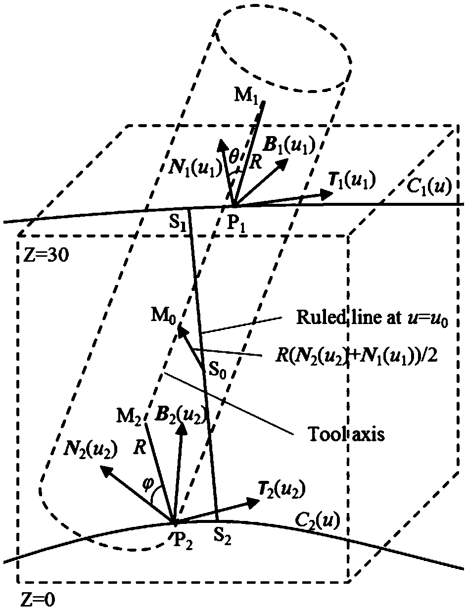
[0029] Such as image 3 As shown, the present invention provides a tool positioning method suitable for side milling non-developable ruled surfaces, which includes the following steps:

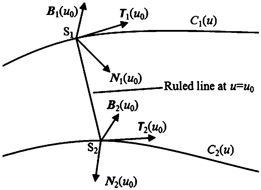
[0030] 1) Select the non-developable ruled surface of the part to be processed, and the upper and lower boundary curves of the non-developable ruled surface are C 1 (u) and C 2 (u).

[0031] 2) Select any straight generatrix S on the non-developable ruled surface 1 S 2 , the straight bus S 1 S 2 The corresponding parameter value is u=u 0 .

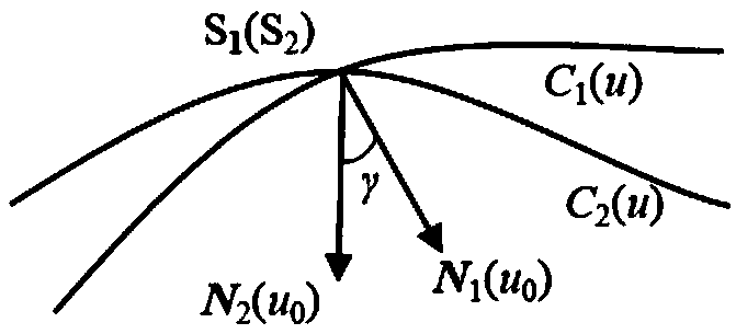
[0032] 3) Straight busbar S in step 2) 1 S 2 Select the unknown parameter u nearby 1 and u 2 , u 1 Corresponding upper boundary curve C 1 Point P on (u) 1 , u 2 Corresponding to the lower boundary curve C 2 Point P on (u) 2 , the upper boundary curve C 1 (u) at P 1 The unit tangent vector of a point is T 1 (u ...


PUM


Abstract

The invention relates to a cutter positioning method for flank milling a non-unfoldable ruled surface. The method comprises the steps that the non-unfoldable ruled surface of a part to be machined is selected, wherein upper and lower boundary curves are C1(u) and C2(u); any one straight generatrix S1S2 on the ruled surface is selected, wherein a corresponding parameter value is u0; unknown parameters u1 and u2 are selected near the generatrix S1S2, wherein the unit tangent vector of the upper boundary curve at a P1 point is T1(u1), the unit tangent vector of the lower boundary curve at a P2 point is T2(u2), the unit vector of a main normal line at the P1 point is N1(u1), the unit vector of a binormal at the P1 point is B1(u1), the unit vector of the main normal line at the P2 point is N2(u2), and the unit vector of the binormal at the P2 point is B2(u2); a relation equation about a M1 point and a M2 point on the cutter axis and the P1 point and the P2 point is determined; after two constraint conditions are added into the equation, four unknown variables u1, u2, theta and phi are solved, then values of the M1 point and the M2 point are calculated, a cutter-axis vector of the cutter is obtained, and the cutter location attitude is determined by combining the cutter tip point M2; all the parameters are traversed along the boundary curves according to the increasing sequences and the appropriate parameter interval till the cutter location attitude of the whole ruled surface is completed.

Description

technical field [0001] The invention relates to a tool positioning method, in particular to a tool positioning method suitable for side milling non-developable ruled surfaces applied in the field of numerical control machine tool processing. Background technique [0002] Currently, if figure 1 As shown, the non-developable ruled surface is different from the developable ruled surface. The magnitude and direction of the normal vectors of each point on the same straight generatrix of the surface are different, and there are twist angles (such as figure 2 As shown), due to the existence of the twist angle, the tool cannot completely fit the surface like the developable ruled surface such as the side of the cone and the side of the cylinder, and is tangent to the surface. No matter how to determine the tool pose, there will always be principle errors. The existing series of mathematically accurate and analytical methods for calculating the tool pose (such as single-point offse...

Claims


Application Information

Patent Timeline
Patent Type & Authority Patents(China)
IPC IPC(8): G05B19/402
CPCG05B19/402G05B2219/36359
Inventor 莫艽关立文王立平陈晃李铁民
Owner TSINGHUA UNIV
Why Eureka
Try Eureka