
Expandable antenna mechanism of torsion spring driven shears-fork annular truss

A ring truss and torsion spring technology is applied in the field of deployable antenna mechanisms, which can solve the problems of few types of ring truss mechanisms, heavy driving motor weight, slow deployment process, etc., and achieves easy engineering manufacturing, relatively large folding, and fast deployment process. Effect

Pending Publication Date: 2016-12-14
YANSHAN UNIV
View PDF6 Cites 4 Cited by
  • Summary
  • Abstract
  • Description
  • Claims
  • Application Information

AI Technical Summary

Problems solved by technology

[0004] Large-scale deployable space-borne antenna is a key technology in the development of satellites. Missions such as electronic reconnaissance, data relay, and ground navigation put forward high-gain requirements for space-borne antennas. Directly increasing the reflector aperture is the best way to increase antenna gain. As an effective way, the existing space-borne deployable antennas mostly use hinged truss-type deployable mechanisms. Ring truss mechanisms are widely used, but there are fewer types of existing ring truss mechanisms, and they have low stiffness and drive Complexity, slow unfolding process and heavy driving motor mass

Method used


Image

  • Expandable antenna mechanism of torsion spring driven shears-fork annular truss
  • Expandable antenna mechanism of torsion spring driven shears-fork annular truss
  • Expandable antenna mechanism of torsion spring driven shears-fork annular truss

Examples


Embodiment Construction

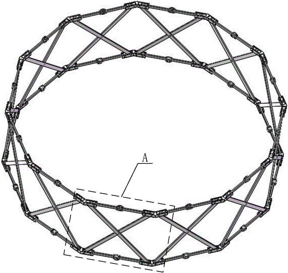
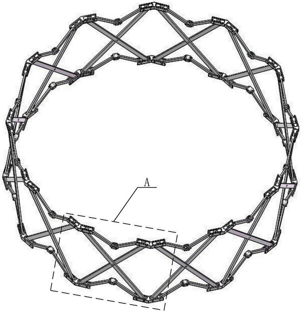
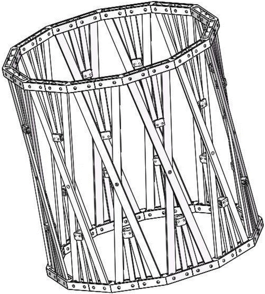
[0022] exist figure 1 , figure 2 and image 3 The three-dimensional schematic diagram of the expandable antenna mechanism of the torsion spring-driven scissor ring truss includes 12 folding units A, each of which has the same structure, and the adjacent folding units pass through the shared upper and lower faceplates connected to form a multifaceted ring truss. The entire torsion spring driven scissor ring truss expandable antenna mechanism is a multi-faceted ring truss structure after being deployed and folded.

[0023] exist Figure 4 , Figure 5 and Figure 6 In the three-dimensional schematic diagram of the folding unit of the deployable antenna mechanism of the torsion spring-driven scissor ring truss, the folding unit A mainly includes four faceplates 1, two scissor rods 2, and four connecting rods 3 and two groups of torsion spring drive components B. The structure of the four faceplates is exactly the same, as Figure 8 As shown, it is a zigzag with a plane up...


PUM


Abstract

The invention discloses an expandable antenna mechanism of a torsion spring driven shears-fork annular truss. The mechanism comprises N folding and unfolding units with completely same structure, and the adjacent folding and unfolding units are connected by shared upper and lower flower discs to form a polygonal annular truss. Each folding and unfolding unit comprises two shears-fork rods, two groups of torsion spring driving assemblies, four connecting rods and four flower discs. All rotating pair axes on the shears-fork rods and the connecting rods in the same folding and unfolding unit are parallel. The mechanism has the characteristics of high rigidity, flexibility in motion and large folding ratio; and by adopting torsion spring driving, the whole mechanism is fast in unfolding and quick in response, and can be applied to communication satellites, space stations and space detectors.

Description

technical field [0001] The invention relates to a deployable antenna mechanism. Background technique [0002] The expandable mechanism originated in the 1960s. It is integrated with prefabricated units and can switch between the initial compact configuration and the expanded configuration in the working state. It generally has two stable states: a fully folded state and a fully expanded state ( working status). With the rapid development of manned spaceflight, earth observation, deep space exploration, and space communication, the size of space mechanisms required in various aerospace projects is getting larger and larger to meet the needs of different space missions. Due to the limitation of the effective space of the tool, it is necessary to design a space expandable mechanism with a large folding ratio. It is in a folded state during the launch and transportation stages and is folded in the fairing. After the spacecraft enters orbit, it will be deployed to the working st...

Claims


Application Information

Patent Timeline
Patent Type & Authority Applications(China)
IPC IPC(8): H01Q1/08
CPCH01Q1/08
Inventor 赵永生韩博许允斗姚建涛刘文兰陈亮亮李相斌
Owner YANSHAN UNIV
Learn More