Connector specially for substation grounding wire ground end

A grounding wire and connector technology, which is applied in substation grounding layout, conductive connection, electrical component connection, etc., can solve the problems of adverse effects on the reliability of power system operation, reliable grounding of installed grounding wires, failure to meet the requirements of five defenses, etc. , to achieve the effect of ensuring safe and reliable operation, safe and reliable grounding, and complete functions

Inactive Publication Date: 2016-12-14
陈志源
View PDF5 Cites 0 Cited by
  • Summary
  • Abstract
  • Description
  • Claims
  • Application Information

AI Technical Summary

Problems solved by technology

[0002] The substation is equipped with a large number of high-voltage electrical equipment for power transformation, power transmission and distribution, and other electrical equipment. In order to prevent induction electricity and sudden incoming electricity, and ensure the personal safety of the staff, the high-voltage electrical equipment for maintenance must be grounded safely and reliably. In the actual production operation, when the ground wire is installed, it cannot be safely and reliably grounded to the ground end. Because there is no special ground wire ground end connected to the pile head on site,

Method used


Image

  • Connector specially for substation grounding wire ground end
  • Connector specially for substation grounding wire ground end
  • Connector specially for substation grounding wire ground end

Examples


Example Embodiment

[0016] In order to make the purposes, technical solutions and advantages of the embodiments of the present invention clearer, the technical solutions in the embodiments of the present invention will be clearly and completely described below with reference to the accompanying drawings in the embodiments of the present invention. , all other embodiments obtained by those of ordinary skill in the art without creative work, all belong to the protection scope of the present invention.
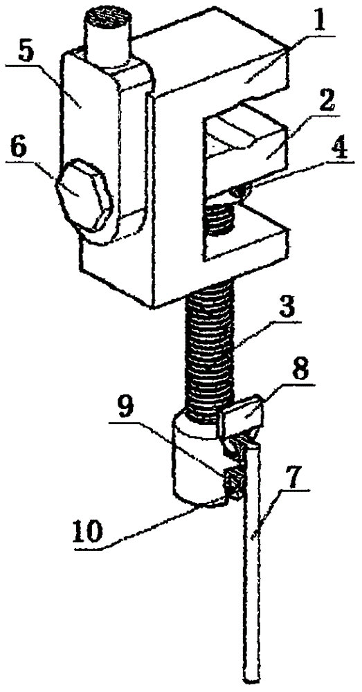
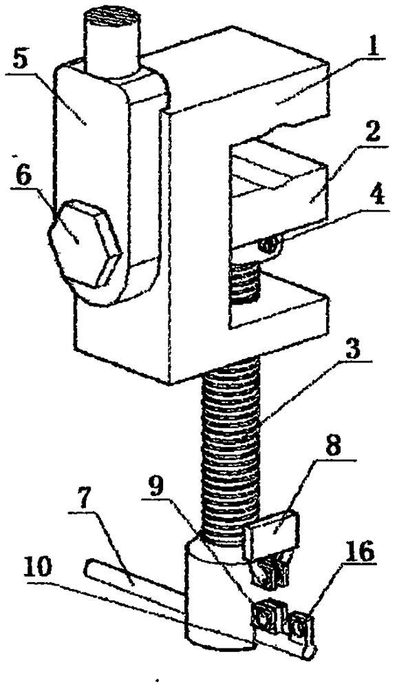
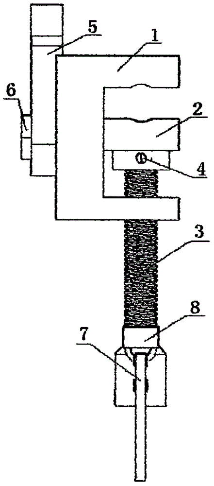
[0017] figure 1 , figure 2 It is a three-dimensional hidden visual style diagram of the southwest isometric of the special connector for the ground end of the substation grounding wire provided by the present invention, image 3 Yes figure 1 The main view of the special connector for the ground end of the substation grounding wire in Figure 4 Yes figure 1 The right view of the special connector for the ground end of the substation grounding wire in Figure 5 Yes figure 1 The structural diagr...


PUM


Abstract

The invention relates to a connector specially for a substation grounding wire ground end, which comprises a body, a movable chuck, a shoulder screw, a screw column, a grounding wire copper nose, a bolt, an operation handle, a program lock, a shaft, an operation handle fixing groove, a linked nut I, a coupling nut, a supporting groove, a lock hole, a fixing hole, an operation handle lock hole, a connection hole I, a grounding wire connection hole, a dent, a groove, a linked nut II, and a connection hole II, wherein the shoulder screw is arranged in the connection hole II via the linked nut II; the screw column is arranged in the dent via the coupling nut to enable the shoulder screw and the movable chuck to be connected; the linked nut I, the linked nut II and the body are connected; the operation handle is arranged in the supporting groove, and the shaft is connected with the operation handle via the fixing hole and the connection hole; the program lock locks the operation handle via the lock hole and the operation handle lock hole; and the operation handle can be embedded in the operation handle fixing groove only when the program lock is opened to execute forward and backward rotation operation. Compared with the prior art, the connector specially for the substation grounding wire ground end of the invention has the advantages of simple structure, simple and convenient operation, reliable and firm performance and the like.

Description

technical field [0001] The invention relates to the technical field of auxiliary equipment for power transmission and transformation equipment, in particular to a special connector for the ground terminal of a substation ground wire. Background technique [0002] The substation is equipped with a large number of high-voltage electrical equipment for power transformation, power transmission and distribution, and other electrical equipment. In order to prevent induction electricity and sudden incoming electricity, and ensure the personal safety of the staff, the high-voltage electrical equipment for maintenance must be grounded safely and reliably. In the actual production operation, when the ground wire is installed, it cannot be safely and reliably grounded to the ground end. Because there is no special ground wire ground end connected to the pile head on site, it is grounded to the ground end and cannot meet the requirements of the five defenses. In the case of live install...

Claims


Application Information

Patent Timeline
IPC IPC(8): H01R11/14H01R4/36H02B5/01
CPCH01R4/366H01R11/14H02B5/01
Inventor 胡立伟陈志源柯宗敏李富强朱海松毛裕义张伟斌方忠竺海波傅海波陈一飞曹毅庄伟国陈惠徐东伟陈家栋
Owner 陈志源
Why Eureka
Try Eureka