Improved high-voltage power distribution cabinet structure

A technology of high-voltage power distribution cabinets and power distribution cabinets, which is applied to the substation/power distribution device shell, electrical components, substation/switch layout details, etc., and can solve the problem of low protection safety factor, short service life and hidden dangers of power distribution cabinets, etc. Problems, to achieve significant waterproof effect, improve service life, and easy maintenance

Inactive Publication Date: 2016-12-14
TAICANG HONGGUANG CONTROLS ELECTRIC APPLIANCE EQUIP
View PDF5 Cites 4 Cited by
  • Summary
  • Abstract
  • Description
  • Claims
  • Application Information

AI Technical Summary

Problems solved by technology

[0002] High-voltage power distribution cabinets are more and more widely used in factories and living areas to achieve power conversion, distribution, and control functions. The existing power distribution cabinets have low protection safety factors and short service life. Users' demand for electric energy is increasing. Power distribution cabinets The capacity of the power distribution cabinet is increasing year by year. If an accident occurs in the power distribution cabinet, the consequences will be serious. The existing power distribution cabinets are fixed by screws, and the rear door is easy to open by mistake. All copper row cables are high voltage, which has hidden dangers. The maintenance and repair of the power distribution cabinet is troublesome. If the temperature in the cabinet is too high, it will affect the use of electrical appliances in the equipment, and the outdoor high-voltage power distribution cabinet is often eroded by rain and rain, and the operation of the vacuum circuit breaker is troublesome.

Method used


Image

  • Improved high-voltage power distribution cabinet structure

Examples


Embodiment Construction

[0015] The preferred embodiments of the present invention will be described in detail below in conjunction with the accompanying drawings, so that the advantages and features of the present invention can be more easily understood by those skilled in the art, so as to define the protection scope of the present invention more clearly.

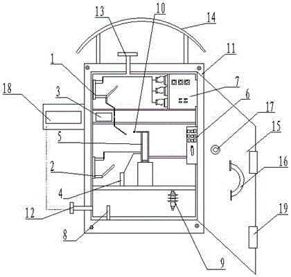
[0016] see figure 1 , the embodiment of the present invention includes:

[0017] The improved high-voltage power distribution cabinet structure includes a power distribution cabinet body. The power distribution cabinet body adopts a cuboid structure, and the material of the cabinet body is made of alloy cast steel. In order to improve the rigidity of the power distribution cabinet body, the A high-voltage cabinet bottom plate is connected to the electric cabinet body. The high-voltage cabinet bottom plate adopts a cuboid structure. The high-voltage cabinet bottom plate and the power distribution cabinet body are connected as a whole by welding to...


PUM


Abstract

The present invention discloses an improved high-voltage power distribution cabinet structure. The structure comprises a power distribution cabinet body, and a cabinet cavity body is arranged in the power distribution cabinet body; a bus cavity is arranged at the top of the cabinet cavity body, a horizontal main bus is arranged, a branch bus is arranged at the lower end of the main bus, and a switch cavity is arranged at the lower end of the bus cavity; an upper portion isolation switch and a lower portion isolation switch are arranged in a switch cavity, a vacuum circuit breaker is connected and arranged between the upper portion isolation switch and the lower portion isolation switch; the upper portion isolation switch is connected with a current transformer, and a voltage transformer is connected with the lower portion isolation switch; and a cable cavity is arranged at the lower end of the switch cavity, and an instrument cavity is arranged at the right side of the bus cavity. The improved high-voltage power distribution cabinet structure is convenient in maintenance and easy to monitor the temperature in the cabinet.

Description

technical field [0001] The invention relates to the field of electric power equipment, in particular to an improved structure of a high-voltage power distribution cabinet. Background technique [0002] High-voltage power distribution cabinets are more and more widely used in factories and living areas to achieve power conversion, distribution, and control functions. The existing power distribution cabinets have low protection safety factors and short service life. Users' demand for electric energy is increasing. Power distribution cabinets The capacity of the power distribution cabinet is increasing year by year. If an accident occurs in the power distribution cabinet, the consequences will be serious. The existing power distribution cabinets are fixed by screws, and the rear door is easy to open by mistake. All copper row cables are high voltage, which has hidden dangers. The maintenance and repair of the power distribution cabinet is troublesome. If the temperature in the ...

Claims


Application Information

Patent Timeline
Patent Type & Authority Applications(China)
IPC IPC(8): H02B1/30H02B1/28H02B1/56
CPCH02B1/30H02B1/28H02B1/565
Inventor 单晓艳
Owner TAICANG HONGGUANG CONTROLS ELECTRIC APPLIANCE EQUIP
Why Eureka
Try Eureka