Rotary knob and display device

A display device, knob technology, applied in electrical components, pulse technology, electronic switches, etc., can solve the problems of low matching degree of electronic technology, low control accuracy, low integration, etc., to improve experience, high control accuracy, Highly integrated effect

Inactive Publication Date: 2016-12-14
BOE TECH GRP CO LTD
View PDF5 Cites 2 Cited by
  • Summary
  • Abstract
  • Description
  • Claims
  • Application Information

AI Technical Summary

Problems solved by technology

[0002] Knobs can be seen everywhere in daily life, but the current knobs are generally mechanical structures, which have the following problems: large volume, low control accuracy; low matching with contemporary electronic technology, and low integration

Method used


Image

  • Rotary knob and display device
  • Rotary knob and display device
  • Rotary knob and display device

Examples


Embodiment 1

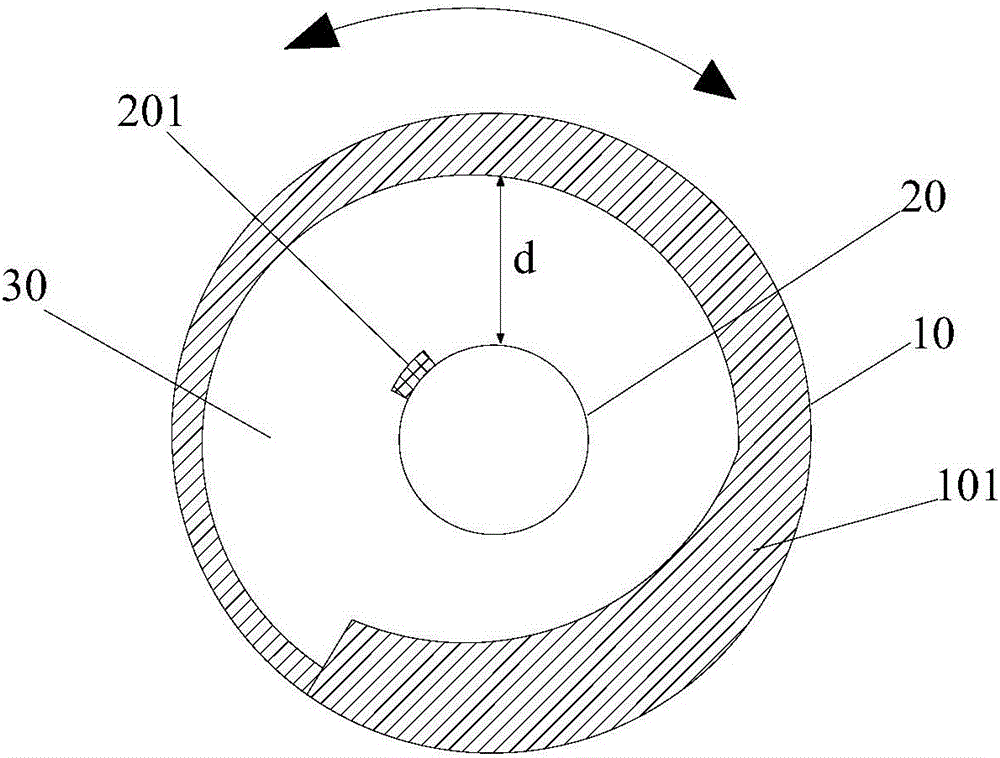
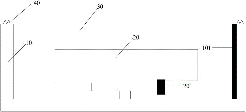
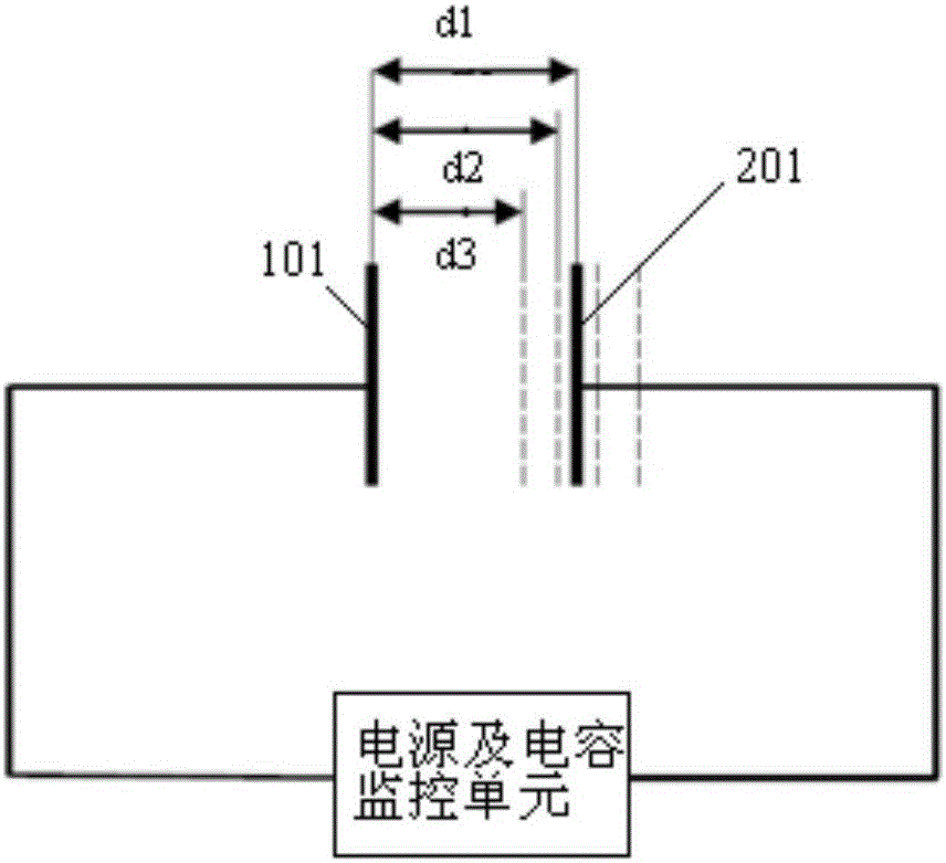
[0026] figure 1 A top view of a knob provided by an embodiment of the present invention. see figure 1 , the knob provided in the embodiment of the present invention includes a first body 10 and a second body 20 that are relatively rotatable. Wherein, a first conductor 101 is provided on a surface of the first body 10 opposite to the second body 20; a second conductor is provided on a surface of the second body 20 opposite to the first body 10 201; the distance d between the first conductor 101 and the second conductor 201 is different at multiple different positions in the direction of rotation, so that the first conductor 101 and the second conductor 201 are rotated to each position. The capacitance formed by the conductor 201 is different in size.

[0027] It can be understood that in the application, by rotating the first body 10 and / or the second body 20 to make the two relatively rotate, the first conductor 101 and the second conductor 201 can be driven to rotate relat...


PUM


Abstract

The invention provides a rotary knob and a display device. The rotary knob comprises a first body and a second body, wherein the first body and the second body can be rotated oppositely; one side, opposite to the second body, of the first body is provided with a first conductor; one side, opposite to the first body, of the second body is provided with a second conductor; and a space between the first conductor and the second conductor at multiple different positions along a rotation direction is different, so that a capacitance formed by the first conductor and the second conductor when being rotated to each of the positions is different. The rotary knob provided by the invention not only has small size, but also has high control precision, high sensitivity, high matching degree with a contemporary electronic technology and high integration level; and by virtue of the rotary knob, an operation function of the display device can be greatly enriched; and the experience of a user is improved.

Description

technical field [0001] The invention belongs to the field of display technology, and in particular relates to a knob and a display device. Background technique [0002] Knobs can be seen everywhere in daily life. However, the current knobs are generally mechanical structures, which have the following problems: large volume, low control accuracy, low compatibility with contemporary electronic technology, and low integration. Contents of the invention [0003] The present invention aims to solve at least one of the technical problems in the prior art, and proposes a knob and a display device. [0004] In order to solve one of the above-mentioned problems, the present invention provides a knob, which includes a first body and a second body that can rotate relative to each other; a first conductor is arranged on the surface of the first body opposite to the second body; A second conductor is provided on the surface of the second body opposite to the first body; the distance b...

Claims


Application Information

Patent Timeline
Patent Type & Authority Applications(China)
IPC IPC(8): H03K17/975
CPCH03K17/975
Inventor 彭锦涛徐智强
Owner BOE TECH GRP CO LTD
Why Eureka
Try Eureka