Contactless power supply system and power receiving device

A technology of power supply system and power receiving device, which is applied in the direction of circuit devices, electric vehicle charging technology, charging stations, etc., can solve the problems of reduced charging efficiency and reduced transmission efficiency, and achieve the effect of suppressing changes in impedance

Active Publication Date: 2019-06-14
IHI CORP
View PDF4 Cites 0 Cited by
  • Summary
  • Abstract
  • Description
  • Claims
  • Application Information

AI Technical Summary

Problems solved by technology

Since the positional relationship between the power transmitting coil and the power receiving coil deviates from the desired position, the coupling coefficient between the coils may change and the transmission efficiency may decrease
[0005] Conventionally, there has been proposed a technique for suppressing a decrease in charging efficiency when a positional deviation between coils occurs (for example, refer to Patent Document 1).
The power supply device (power transmission device) of Patent Document 1 changes the frequency of AC power supplied from the inverter circuit (power supply) to the power transmission coil when the transmission efficiency is lowered due to positional displacement.

Method used


Image

  • Contactless power supply system and power receiving device
  • Contactless power supply system and power receiving device
  • Contactless power supply system and power receiving device

Examples


no. 1 approach

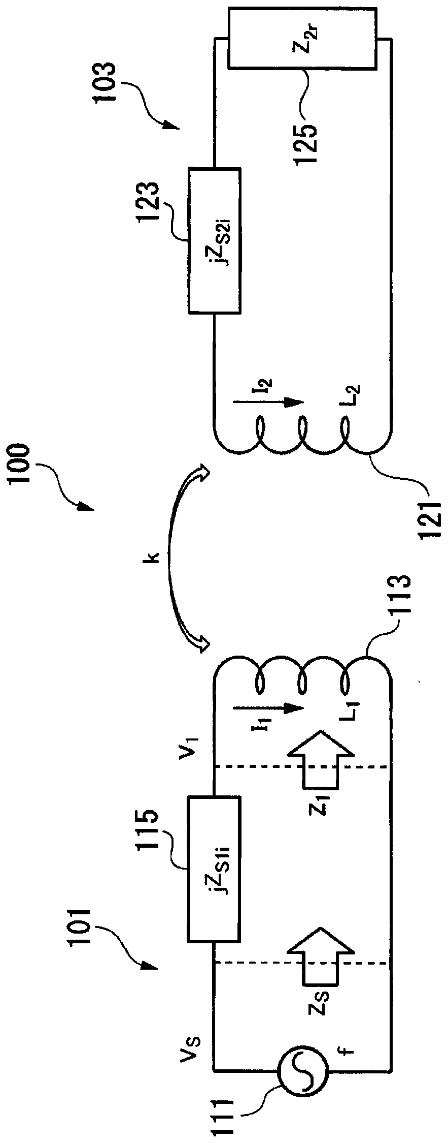
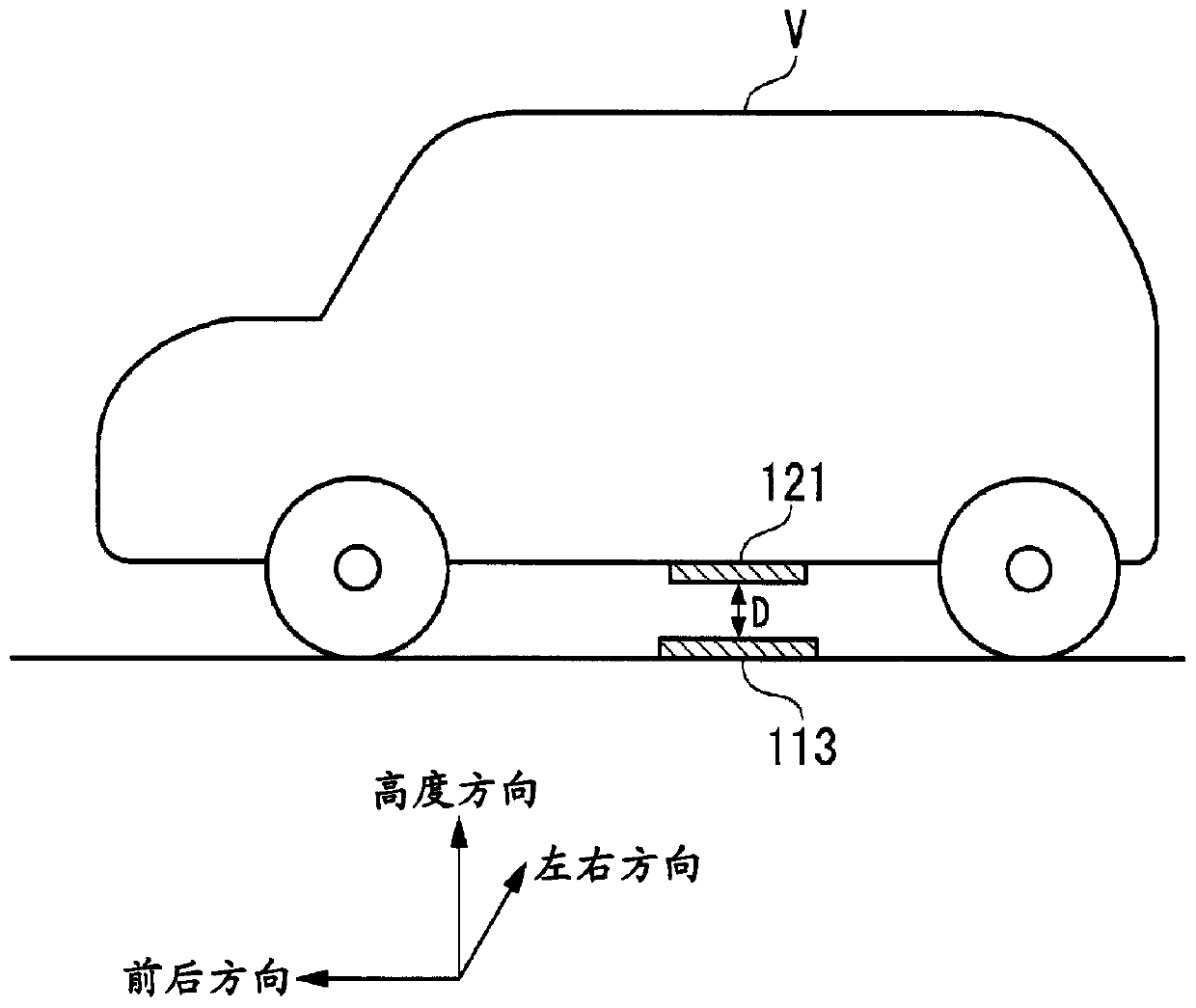
[0071] figure 1 It is a circuit diagram of the contactless power supply system of 1st Embodiment of this invention. The contactless power supply system 100 includes a power transmission device 101 and a power reception device 103 . The power transmitting device 101 includes a power transmitting coil 113 described below, and the power receiving device 103 includes a power receiving coil 121 described below. The power transmitting device 101 transmits electric power to the power receiving device 103 in a non-contact manner through magnetic coupling between coils. A method of transmitting electric power using magnetic coupling between coils is, for example, an electromagnetic induction method or a magnetic resonance method. Examples of applications of the contactless power supply system 100 include electric vehicles (vehicles), mobile bodies such as underwater vehicles, charging systems and drive systems for home appliances or medical equipment. The power transmission coil 113...

no. 2 approach

[0154] In the first embodiment, the case where the element 115 having an imaginary impedance is connected in series to the power transmitting coil 113 and the element 123 having an imaginary impedance is connected in series to the power receiving coil 121 has been described. However, in the second embodiment, A case where an element having an imaginary impedance is connected in parallel to each of the power transmitting coil and the power receiving coil will be described.

[0155] The contactless power supply system 200 of the second embodiment includes a power transmission device 201 and a power reception device 203 . The power transmission device 201 includes a power transmission coil 213 to which AC power is input from a power source 211 , an element (series element on the power transmission side) 215 , and an element (parallel element on the power transmission side) 217 ​​. The power receiving device 203 includes a power receiving coil 221 , an element (series element on t...


PUM


Abstract

A non-contact power supply system (100) includes a power transmission device (101) and a power reception device (103). The power transmission device includes a power transmission coil (113) to which AC power of a certain frequency is input from a power supply (111). The power receiving device includes: a power receiving coil (121), which is magnetically coupled with the power transmitting coil through a certain coupling coefficient; and a first power receiving side series element (123), which is connected in series with the power receiving coil and has an imaginary impedance jZS2i. In this contactless power supply system, the frequency and the imaginary impedance are determined so that when the coupling coefficient changes, the impedance when the power receiving side is viewed from the power source is independent of the coupling coefficient.

Description

technical field [0001] The invention relates to a non-contact power supply system and a power receiving device. [0002] This application claims priority based on Japanese Patent Application No. 2014-96353 filed in Japan on May 7, 2014 and Japanese Patent Application No. 2014-181419 filed in Japan on September 5, 2014, and the contents thereof are incorporated herein. Background technique [0003] In recent years, there has been known a non-contact power feeding system that uses electromagnetic induction, magnetic resonance, or the like to feed power from a power transmitting device including a power transmitting coil to a power receiving device including a power receiving coil. In this system, the magnetic flux generated by the power transmitting coil interlinks with the power receiving coil, whereby electric power is transmitted between the coils. Therefore, the efficiency of power transmission (transmission efficiency) is affected by the positional relationship between t...

Claims


Application Information

Patent Timeline
Patent Type & Authority Patents(China)
IPC IPC(8): H02J50/10
CPCB60L53/12H02J50/12H02J50/80H02J50/90Y02T10/70Y02T10/7072Y02T90/14H02J50/10H02J50/60
Inventor 中村寿夫村山隆彦荒木淳
Owner IHI CORP
Why Eureka
Try Eureka