Distributor and signal generating system using same

A technology of signal generation and signal generator, which is applied in the direction of waveguide devices, circuits, connecting devices, etc., can solve the problems of signal level difference, impedance change, interference, etc., to reduce errors, suppress impedance changes, and suppress signal voltage The effect of the adjustment

Active Publication Date: 2021-09-07
ANRITSU CORP
View PDF6 Cites 0 Cited by
  • Summary
  • Abstract
  • Description
  • Claims
  • Application Information

AI Technical Summary

Problems solved by technology

[0006] However, in the simultaneous measurement of a plurality of measurement terminals distributed by the existing distributor, the impedance of other measurement terminals or signal input terminals occurs due to impedance mismatch due to poor contact of the measurement terminal connected to the object to be measured. As a result, the signal level of a plurality of distributed measurement signals differs, for example, a difference of 1 dB or more, and there is a problem that accurate simultaneous measurement cannot be performed.

Method used


Image

  • Distributor and signal generating system using same
  • Distributor and signal generating system using same
  • Distributor and signal generating system using same

Examples


no. 1 Embodiment approach

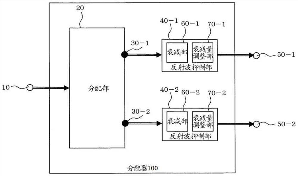
[0033] First, refer to figure 1 , the structure of the dispenser 100 according to the present invention will be described.

[0034] Such as figure 1 As shown, the distributor 100 of this example includes an input terminal 10, a distribution unit 20, a distribution unit output 30-1, 30-2, ... 30-n, and reflected wave suppression units 40-1, 40-2, ... 40 -n, output terminals 50-1, 50-2, ... 50-n, attenuation units 60-1, 60-2, ... 60-n, attenuation adjustment units 70-1, 70-2, ... 70 -n. In addition, it is possible to have a configuration in which the attenuation adjustment units 70-1, 70-2, ... 70-n are omitted.

[0035] A high-frequency signal from an external signal source is input to the input terminal 10 . Here, high-frequency signals, for example, from several MHz to several tens of GHz are processed. The signal source is, for example, a signal generator that generates a high-frequency signal of an arbitrary frequency, an arbitrary signal level, and an arbitrary modula...

no. 2 Embodiment approach

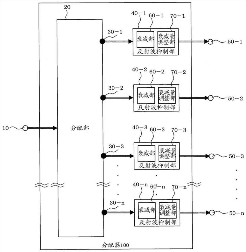
[0049] Next, refer to figure 2 , other structures of the dispenser 100 according to the present invention will be described.

[0050] Such as figure 2 As shown, except for the n ports of the output terminals 50-1, 50-2, 50-3, ... 50-n, they are the same as those of the first embodiment, so the description is omitted. In this way, the output terminals are not limited to 2 or 4 ports, but may be n ports.

no. 3 Embodiment approach

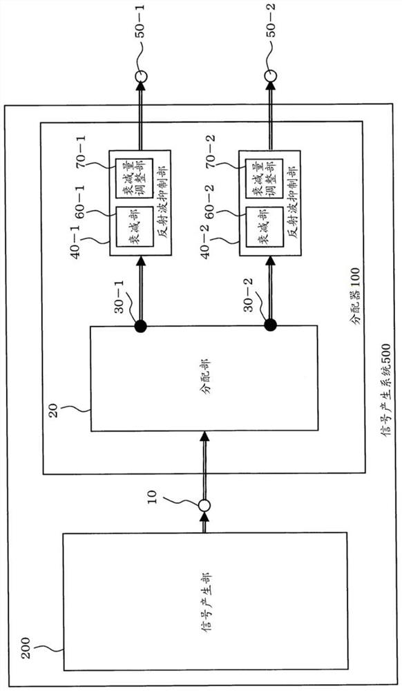
[0052] Next, refer to image 3 , the operation of the signal generating system 500 using the above-mentioned distributor 100 will be described.

[0053] In the signal generation system 500 of this example, for example, a signal generator 200 for generating a high-frequency signal of an arbitrary frequency, an arbitrary signal level, and an arbitrary modulation method is connected to the input terminal 10 of the distributor 100 .

[0054] The operation of the dispenser 100 is the same as that of the first embodiment, so description is omitted. In addition, in the signal generating system 500, image 3 The output terminals shown are not limited to 2 ports and can also be figure 2 n ports as shown.


PUM


Abstract

The present invention provides a distributor and a signal generating system capable of accurately evaluating a test object without affecting the impedance of a test terminal of the test object. The present invention is a distributor (100) provided with an input terminal (10) and a plurality of output terminals (50‑1, 50‑2, ... 50‑n), which includes: a distribution part (20) for input to input terminals The high-frequency signals are distributed and output from multiple distribution parts (30-1, 30-2, ... 30-n); and multiple reflected wave suppression parts (40-1, 40-2, ... 40-n), respectively connected to a plurality of distribution part outputs, used to suppress the reflected wave reflected by the output terminal side, and output the output of a plurality of reflected wave suppressing parts from the output terminal.

Description

technical field [0001] The invention relates to a distributor for processing high-frequency signals. Background technique [0002] A splitter is also called a power splitter, a power divider, a splitter, etc., and is a device that distributes an input high-frequency signal to multiple outputs. For example, high-frequency signals from several MHz to tens of GHz are processed. [0003] As an example of a distributor application, it is used to distribute an input high-frequency signal to a plurality of receiving units in a wireless communication device. In the field of measurement, for example, the output signal of the signal generator is input to the distributor, and the high-frequency signal is distributed, so that the signals distributed to a plurality of measured objects are respectively sent. For example, the following patent documents are known figure 1 The allocators exposed in . And, the structure example of the existing allocator is shown in Figure 12 . [0004]...

Claims


Application Information

Patent Timeline
Patent Type & Authority Patents(China)
IPC IPC(8): H01P5/16
CPCH01P1/227H01P5/04H01P5/12H01P1/222H01P5/16
Inventor 黑岩祥浩
Owner ANRITSU CORP
Why Eureka
Try Eureka