Anti-pollution air floating vibration filtering structure

A vibration filtration, anti-pollution technology, applied in the direction of moving filter element filters, filtration separation, separation methods, etc., can solve the problems of filtration efficiency to be improved, filter plate clogging, etc., to achieve the effect of ingenious structural design and improved filtration effect.

Inactive Publication Date: 2016-12-21
WUXI LIANGHUI ENVIRONMENTAL PROTECTION MACHINERY CO LTD
View PDF7 Cites 1 Cited by
  • Summary
  • Abstract
  • Description
  • Claims
  • Application Information

AI Technical Summary

Problems solved by technology

Because the above-mentioned vibrating filter structure is only equipped with air flotation tubes at the bottom of the filter barrel, the upper part of the filter plate

Method used


Image

  • Anti-pollution air floating vibration filtering structure
  • Anti-pollution air floating vibration filtering structure

Examples


Example Embodiment

[0014] The specific embodiments of the present invention will be further described below in conjunction with the accompanying drawings.

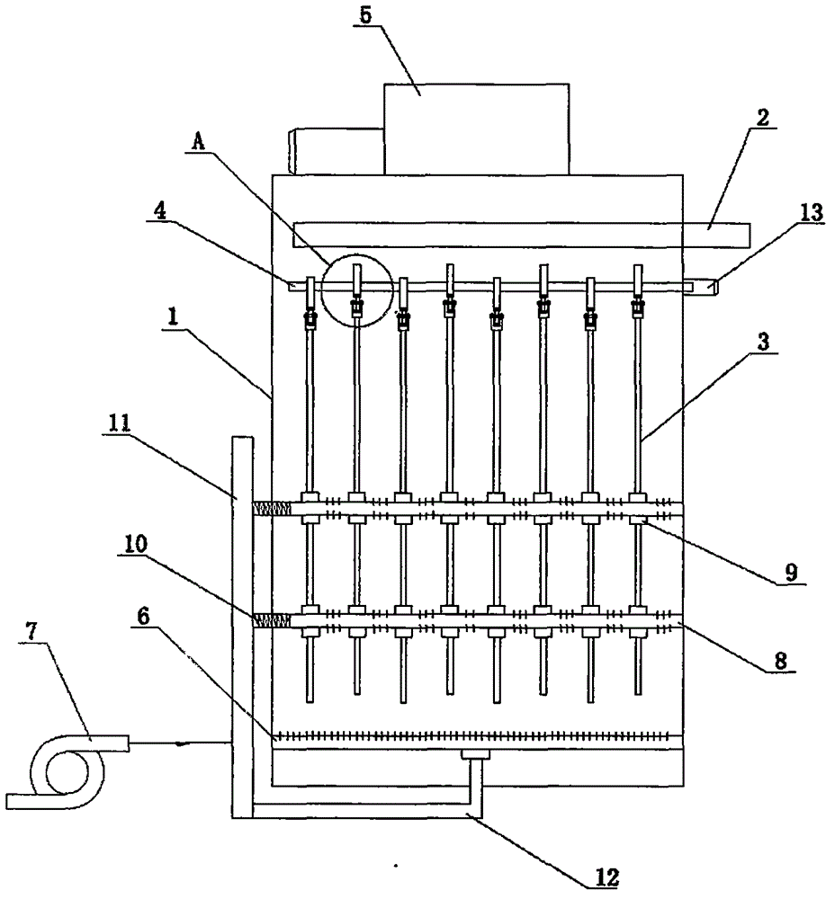
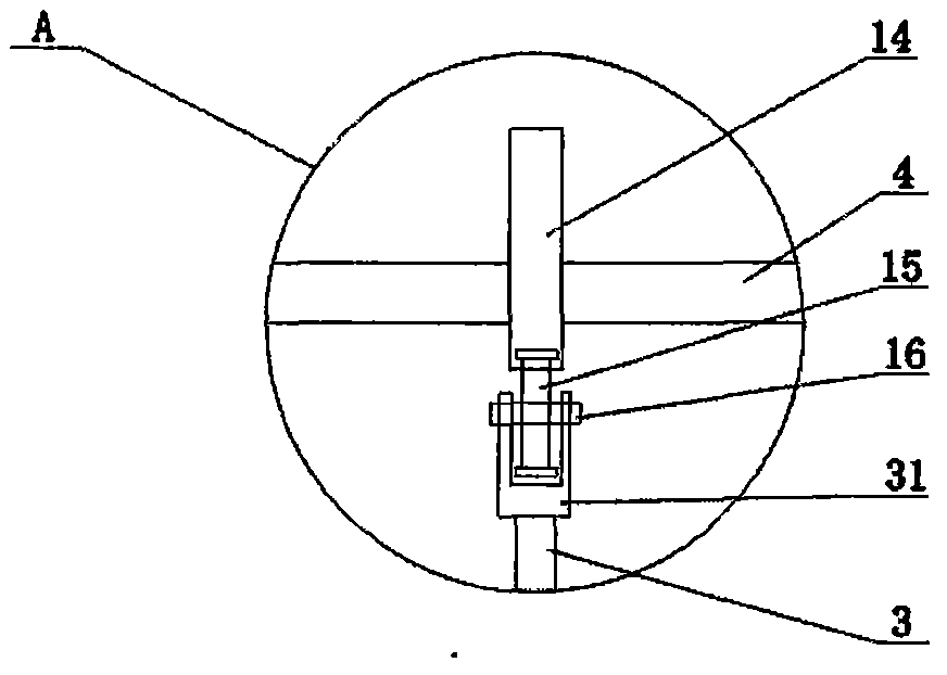
[0015] Such as figure 1 , figure 2 As shown, the anti-pollution air-floating and vibrating filter structure of this embodiment includes a filter barrel 1. An outlet pipe 2 and a plurality of parallel filter plates 3 are provided in the filter barrel 1, and a vibrator 5 is provided on the outside of the top of the filter barrel 1. , The bottom of the inner cavity is provided with a fixed air flotation pipe 6 with air holes, the fixed air flotation pipe 6 is connected with the air pump 7 outside the filter barrel 1, and the upper end of the filter plate 3 is provided with a U-shaped mounting block 31. The roller 15 is installed through the rotating shaft 16, and the roller 15 is connected with the cam 14. The cam 14 is fixedly connected to the driving rod 4. The end of the driving rod 4 extends out of the filter barrel 1 and a driving motor 13 i...


PUM


Abstract

The invention relates to an anti-pollution air floating vibration filtering structure which comprises a filtering bucket, a guide-out pipe and a plurality of parallel filtering plates are arranged in the filtering bucket, a vibrator is arranged on the outer side of the top of the filtering bucket, a fixed air floating pipe with air holes is arranged at the bottom of an inner cavity of the filtering bucket and is connected with an air pump on the outer side of the filtering bucket, a roller is rotationally mounted at the upper end of each filtering plate, and the rollers are in matched connection with cams. The cams are fixedly connected to a driving rod, and one end of the driving rod stretches out of the filtering bucket and is provided with a driving motor. When the driving rod rotates, the cams and the rollers drive the filtering plates to do ascending and descending motion, and the ascending and descending motion of the adjacent filtering plates is opposite in direction. Floating air floating pipes with air holes are further vertically arranged in the filtering bucket, penetrate through the filtering plates and are fixedly connected with the filtering plates through connecting sleeves, the ends of the floating air floating pipes are connected with an air inlet pipe through telescopic hoses, the air inlet pipe is vertically arranged on the outer side of the filtering bucket and connected with the air pump, and the lower end of the air inlet pipe is connected with the fixed air floating pipe through a bottom guide pipe.

Description

technical field [0001] The invention relates to the technical field of environmental protection equipment, in particular to water environment protection and treatment equipment, in particular to anti-pollution vibration filtering equipment. Background technique [0002] In the process of water environment treatment, filtration and separation technology is usually used to purify sewage. The commonly used equipment is vibration filtration equipment, and air flotation vibration filtration equipment is one of them. In the air flotation vibration filter equipment, the vibration filter structure is a filter bucket, in which there are multi-fast parallel filter plates, and an air flotation tube is set under the filter plate, and the air flotation tube is connected to the air pump; when working, the filter plate Vibration filtration is carried out and air bubbles are generated upwards. The function of the air bubbles is to improve the filtration effect on the one hand, and to avoid ...

Claims


Application Information

Patent Timeline
IPC IPC(8): B01D33/03B01D33/37B01D33/68
Inventor 朱建华薛慧忠
Owner WUXI LIANGHUI ENVIRONMENTAL PROTECTION MACHINERY CO LTD
Why Eureka
Try Eureka