Tooth head structure used for waste treatment

A tooth head and waste product technology, which is applied in the field of tooth head structure for waste product treatment, can solve problems such as unreasonable structural design, easy damage to the tooth head structure, and damage to the tooth head structure, and achieve reasonable structure, extended service life, and firmness Good results

Inactive Publication Date: 2016-12-21
ZHEJIANG PACIFIC MACHINERY CO LTD
View PDF10 Cites 1 Cited by
  • Summary
  • Abstract
  • Description
  • Claims
  • Application Information

AI Technical Summary

Problems solved by technology

After the mechanical teeth of the existing shredder are connected with the drive pivot, they collide with waste products such as trees and garbage during work, thereby crushing the objects; however, the mechanical teeth of the existing shredder are made of hard metal The structure of the tooth head is easily damaged under the impact and vibration of the material. Even if the working head of the tooth head is made of hard alloy materials, but the structural design is not reasonable enough, it is easy to cause damage to other parts of the tooth head. The impact of the material will damage the entire tooth head structure, and often need to replace the tooth head, which will affect the work efficiency and increase the cost of use

Method used


Image

  • Tooth head structure used for waste treatment
  • Tooth head structure used for waste treatment
  • Tooth head structure used for waste treatment

Examples


Embodiment Construction

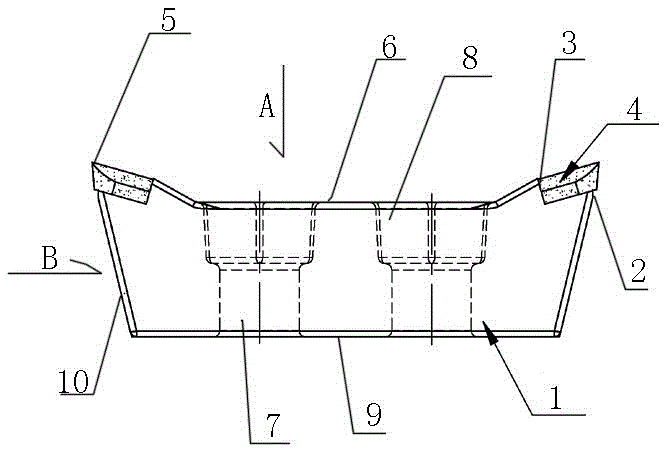
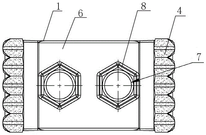
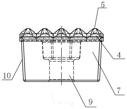
[0010] The present invention will be described in detail below in conjunction with accompanying drawing: Figure 1-3 As shown, a tooth head structure for waste product treatment according to the present invention includes a rectangular block body 1, and the upper two symmetrical long end sides of the block body 1 are respectively provided with upturned The tooth end 2 is provided with a vertically elongated notch 3 from top to bottom on the tooth end 2, and at least four cemented carbide blocks 4 arranged side by side are welded in sequence in the notch 3, and each block The head ends of the tungsten carbide block 4 are each in a slightly upturned pointed shape 5; the top of the briquetting body 1 is a working plane 6, and the middle position of the working plane 6 is provided with two positioning channels evenly distributed along the center line. hole 7, and two hexagonal nut holes 8 on the same hole center line as the respective positioning through holes 7 are arranged on th...


PUM


Abstract

The invention discloses a tooth head structure used for waste treatment. The tooth head structure comprises a cuboid-shaped pressing block body. Tooth end parts warped upwards are arranged on the two symmetrical long end sides of the upper face of the pressing block body correspondingly, and a transverse rectangular notch is formed in each tooth end part from top to bottom. At least four cemented carbide blocks arranged side by side are sequentially connected into each notch in a welded mode, and the head end of each cemented carbide block is in a sharp corner shape which is warped upwards slightly. The upper surface of the pressing block body is a working plane. Two positioning through holes evenly distributed along the center line are formed in the middle position of the working plane. The working plane is further provided with two hexagonal nut holes with the respective positioning through holes located in the same hole center line. An assembling plane is arranged on the lower surface of the pressing block body. The area of the upper surface of the pressing block body is larger than that of the lower surface of the pressing block body. Oblique side edges which are shrunken inwards from top to bottom are formed on the four side edges of the pressing block body correspondingly, so that a positioning assembly shape is formed. The tooth head structure has the characteristics that the structure is reasonable, using and installing are convenient, the whole tooth head structure is good in firmness, abrasion resistance is high, and therefore the working efficiency is improved, and the service life is prolonged.

Description

technical field [0001] The invention relates to a tooth head structure for waste product treatment, which belongs to the field of crushing mechanical equipment for waste product treatment. Background technique [0002] Shredder is a common waste processing equipment, usually used to crush waste, wood, gravel or bulk waste and so on. After the mechanical teeth of the existing shredder are connected with the drive pivot, they collide with waste products such as trees and garbage during work, thereby crushing the objects; however, the mechanical teeth of the existing shredder are made of hard metal The structure of the tooth head is easily damaged under the impact and vibration of the material. Even if the working head of the tooth head is made of hard alloy materials, but the structural design is not reasonable enough, it is easy to cause damage to other parts of the tooth head. The impact of materials damages the structure of the entire tooth head, and it is often necessary ...

Claims


Application Information

Patent Timeline
Patent Type & Authority Applications(China)
IPC IPC(8): B02C18/18B02C23/00
CPCB02C18/18B02C18/0084B02C23/00B02C2201/06B02C2210/02
Inventor 周志建
Owner ZHEJIANG PACIFIC MACHINERY CO LTD
Why Eureka
Try Eureka