Automatic positioning device of automobile bumper

An automobile bumper and automatic positioning technology, which is applied in positioning devices, large fixed members, clamping, etc., can solve the problems of poor automaticity and adjustability of positioning pins, inability to perform precise positioning and clamping, low positioning and processing accuracy, etc. problems, to achieve the effect of low labor intensity, effective control and high positioning accuracy

Active Publication Date: 2016-12-21
FOSHAN PRATIC CNC SCI & TECH
View PDF6 Cites 2 Cited by
  • Summary
  • Abstract
  • Description
  • Claims
  • Application Information

AI Technical Summary

Problems solved by technology

[0002] At present, in the processing of automobile bumpers, when the workpiece is clamped, the workpiece is first positioned on the turntable, fixed and positioned by the clamping device and the positioning device, and the workpiece is processed after the clamping is completed. Therefore It is necessary to use positioning blocks or positioning pins for positioning, otherwise the length direction of the processed workpiece cannot be positioned and clamping errors will occur; but for the positioning holes on the processing workpiece generally correspond to the positioning positions of the positioning pins on the turntable, there are still up and down Position deviation, and the current positioning pins are poor in automation and adjustability, and often need to be adjusted manually, and accurate positioning and clamping cannot be performed, resulting in low positioning and machining accuracy, complicated operation and low flexibility. When the positioning hole is processed, it is necessary to manually disassemble and assemble the positioning pin many times, resulting in long processing time, poor continuity of operation, high labor intensity, and low operational safety.

Method used


Image

  • Automatic positioning device of automobile bumper
  • Automatic positioning device of automobile bumper
  • Automatic positioning device of automobile bumper

Examples


Embodiment Construction

[0021] The technical solutions of the present invention will be further described below in conjunction with the accompanying drawings and through specific implementation methods.

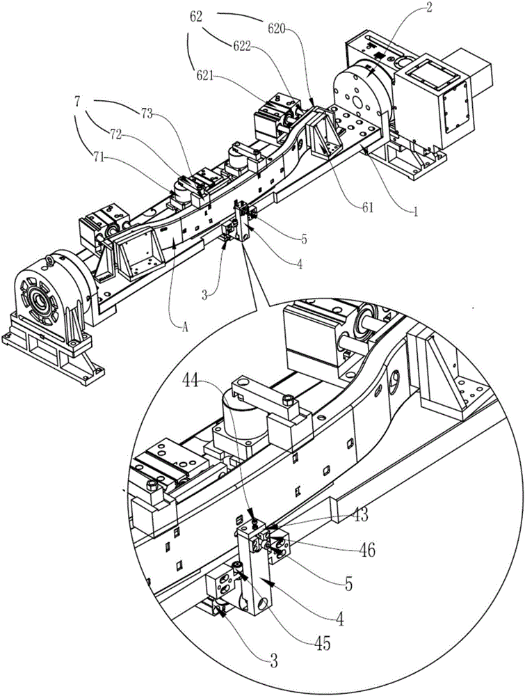
[0022] like figure 1 As shown, an automatic positioning device for an automobile bumper is installed on a machine tool for processing automobile bumpers, and includes a turntable and a positioning mechanism for rotating the workpiece. Installed between the four rotary shafts 2, the four rotary shafts 2 control the rotation of the connecting plate 1;

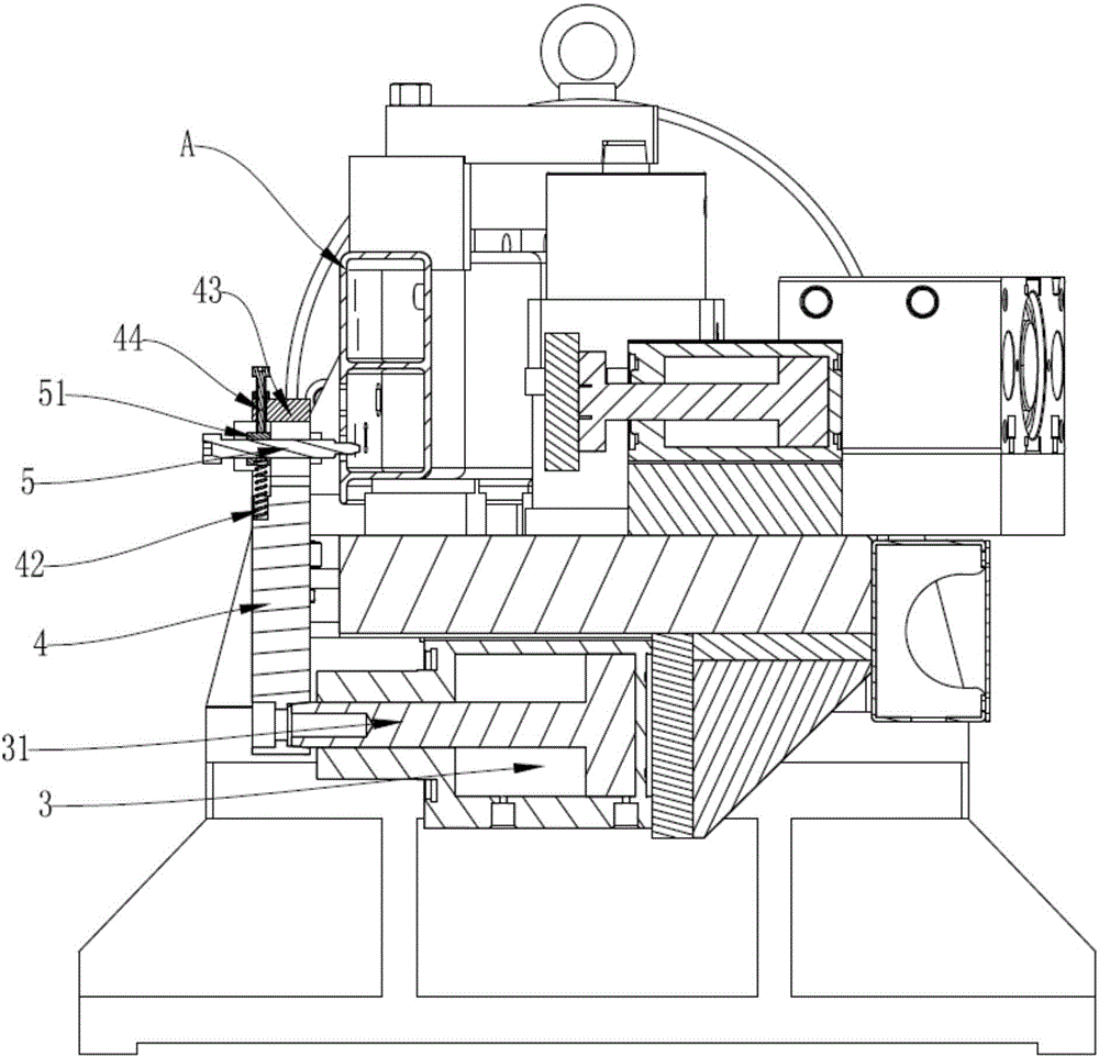
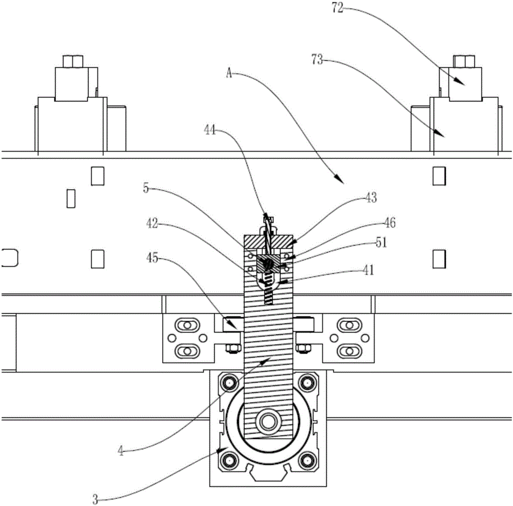
[0023] like figure 2 and image 3 As shown, the positioning mechanism includes a horizontal rotation cylinder 3, a swing arm 4, a first positioning pin 5 and a height adjustment device; the horizontal rotation cylinder 3 is fixedly arranged on the bottom surface of the connecting plate 1, and the horizontal rotation cylinder 3 The end of the horizontal rotation piston rod 31 is connected with the swing arm 4, and the swing arm 4 can rotate along th...


PUM


Abstract

An automatic positioning device of an automobile bumper comprises a rotary table and a positioning mechanism. The positioning mechanism comprises a transverse rotary air cylinder, a swinging arm, a first positioning pin and a height adjustment device, wherein the tail end of a transverse rotary piston rod of the transverse rotary air cylinder is connected with the swinging arm; a U-shaped hole groove is formed in the other end of the swinging arm, and a first positioning pin penetrates through the U-shaped hole groove so as to divide the U-shaped hole groove into an upper groove area and a lower groove area; a spring of the height adjustment device is arranged in the lower groove area; a first fixing block and a lead screw of the height adjustment device are arranged in the upper groove area; the first fixing block is arranged at the top of the upper groove area; the lead screw penetrates through the first fixing block and extends into the upper groove area; the first positioning pin is fixedly installed in the U-shaped hole groove through a second fixing block; and the lead screw spirally downwards presses the second fixing block and the spring to adjust the height of the first positioning pin. According to the automatic positioning device of the automobile bumper, automatic positioning and avoiding of the positioning pin are realized, the structure is simple, operation and control are simple and convenient, machining flexibility is higher, machining efficiency is high, positioning accuracy is effectively controlled, operation continuity is high, and safety is high.

Description

technical field [0001] The invention relates to the technical field of automobile parts processing machinery, in particular to an automatic positioning device for automobile bumpers. Background technique [0002] At present, in the processing of automobile bumpers, when the workpiece is clamped, the workpiece is first positioned on the turntable, fixed and positioned by the clamping device and the positioning device, and the workpiece is processed after the clamping is completed. Therefore It is necessary to use positioning blocks or positioning pins for positioning, otherwise the length direction of the processed workpiece cannot be positioned and clamping errors will occur; but for the positioning holes on the processing workpiece generally correspond to the positioning positions of the positioning pins on the turntable, there are still up and down Position deviation, and the current positioning pins are poor in automation and adjustability, and often need to be adjusted m...

Claims


Application Information

Patent Timeline
Patent Type & Authority Applications(China)
IPC IPC(8): B23Q3/08B23Q1/26
CPCB23Q1/265B23Q3/08
Inventor 叶青健刘世泉李爱军
Owner FOSHAN PRATIC CNC SCI & TECH
Why Eureka
Try Eureka