
Pneumatic reciprocating clamping device

A clamping device, reciprocating technology, applied in vices, manufacturing tools, etc., can solve the problems of low efficiency, time-consuming and laborious, etc., and achieve the effect of reducing dust entry, reducing wear and prolonging service life

Inactive Publication Date: 2016-12-21
ZHEJIANG WILLING TECH
View PDF10 Cites 2 Cited by
  • Summary
  • Abstract
  • Description
  • Claims
  • Application Information

AI Technical Summary

Problems solved by technology

Common clamping devices are manually tightened to achieve clamping, which is time-consuming, laborious and inefficient

Method used


Image

  • Pneumatic reciprocating clamping device

Examples


Embodiment Construction

[0012] The present invention will be further described in detail below in conjunction with the accompanying drawings and examples. The following examples are explanations of the present invention and the present invention is not limited to the following examples.

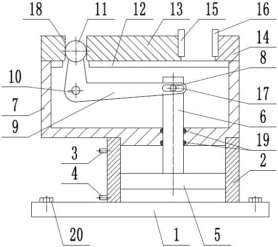
[0013] Such as figure 1 As shown, a pneumatic reciprocating clamping device includes a base 1, a cylinder body 2, an upper valve port 3, a lower valve port 4, a piston 5, a piston rod 6, a supporting seat 7, a dial pin 8, and an L-shaped lever 9. Support shaft 10, ball head 11, guide rail 12, movable jaw 13, fixed jaw 14, movable clamping backing plate 15, fixed clamping backing plate 16, the cylinder body 2 is fixed on the base 1, and the Mounting screws 20 are arranged on the base 1 , which is beneficial to the quick installation of the base 1 . The upper valve port 3 is arranged on the upper end of the cylinder body 2 , the lower valve port 4 is arranged on the lower end of the cylinder body 2 , and the supporti...


PUM


Abstract

The invention provides a pneumatic reciprocating clamping device and belongs to the technical field of machining. The pneumatic reciprocating clamping device comprises an L-shaped lever, a ball, a movable jaw and a fixed jaw. An upper valve port is arranged at the upper end of a cylinder block. A lower valve port is arranged at the lower end of the cylinder block. A piston is arranged inside the cylinder block in an up-down sliding mode. A piston rod is arranged on a bearing support in an up-down sliding mode, and the lower end of the piston rod is fixedly connected with the piston. A shifting pin is fixed to the upper end of the piston rod. The middle end of the L-shaped lever is hinged to a fulcrum. The shifting pin is inserted into a U-shaped groove formed in one end of the L-shaped lever. The other end of the L-shaped lever is provided with the ball. The movable jaw is arranged on a guide rail in a left-right sliding mode. An inserting groove is formed in the movable jaw. The ball is inserted into the inserting groove of the movable jaw. The fixed jaw is fixed to the right end of the bearing support. A movable clamping pad plate is arranged at the right end of the movable jaw. A fixed clamping pad plate is arranged at the left end of the fixed jaw. By adoption of the pneumatic reciprocating clamping device, a workpiece can be clamped and released fast, the structure is simple, and the efficiency is high.

Description

technical field [0001] The invention relates to the technical field of machining, in particular to a pneumatic reciprocating clamping device. Background technique [0002] Machining refers to the process of changing the shape or performance of a workpiece through a mechanical device. According to the difference in processing method, it can be divided into cutting processing and pressure processing. In the production process, the process of changing the shape, size, position and nature of the production object to make it a finished or semi-finished product is called a process. It is an essential part of the production process. The process can be divided into casting, forging, stamping, welding, machining, assembly and other processes. The mechanical manufacturing process generally refers to the sum of the machining process of parts and the assembly process of machines. Other processes are called auxiliary processes. Processes, such as transportation, storage, power supply,...

Claims


Application Information

Patent Timeline
IPC IPC(8): B25B1/02B25B1/18
CPCB25B1/02B25B1/18
Inventor 蒋文星杨桂灿黄国荣
Owner ZHEJIANG WILLING TECH
Learn More