Traction/impact device

A buffer device and tension technology, applied in the direction of buffer, traction device, transportation and packaging, etc., can solve the problems of complexity, long structure of tension/impact buffer device, loud noise, etc., and achieve the effect of compact structure

Inactive Publication Date: 2016-12-21
VOITH PATENT GMBH
View PDF8 Cites 5 Cited by
  • Summary
  • Abstract
  • Description
  • Claims
  • Application Information

AI Technical Summary

Problems solved by technology

However, the solution known from this prior art has the disadvantage that it only makes sense for push operations
[0005] Disadvantages of the solution known from DE 363 03 60 A1 are in particular that two separate coil s

Method used


Image

  • Traction/impact device
  • Traction/impact device
  • Traction/impact device

Examples


Example Embodiment

[0051] The arrangement and design of the force transmission element 3 already mentioned above in relation to the damper housing 4 for the transmission of tensile or compressive forces occurring during operation to the damper mechanism 2 or to the damper housing 4, if required, is such that the force The transmission element 3 can be moved relative to the damper housing 4 in both the tension direction A and the compression direction B. This movement of the force-transmitting element 3 relative to the damper housing 4 can also be achieved in particular by figure 1 and figure 2 and image 3 Comparing with each other, it can be seen that in figure 2 and image 3 An exemplary embodiment of a tension / impact cushioning device according to the invention under load is shown in .

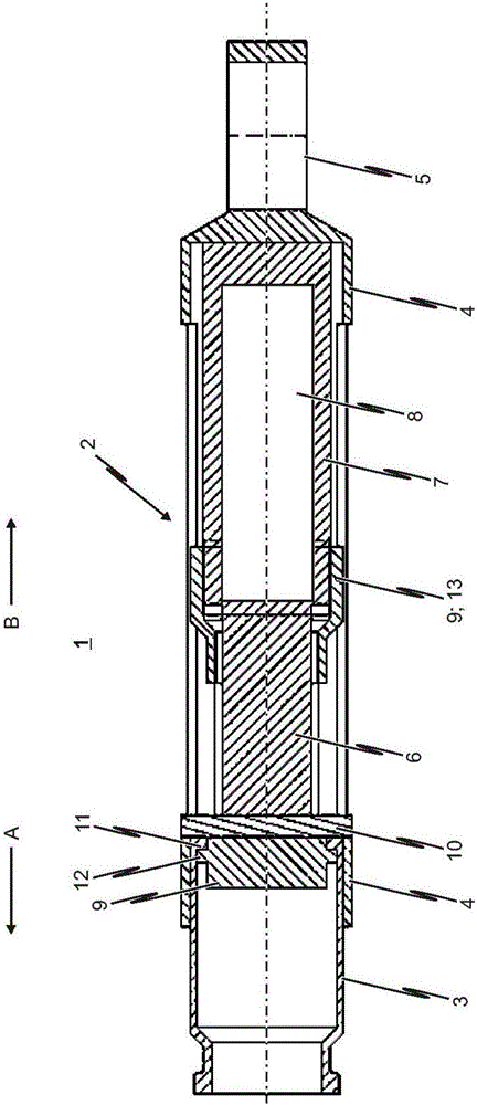
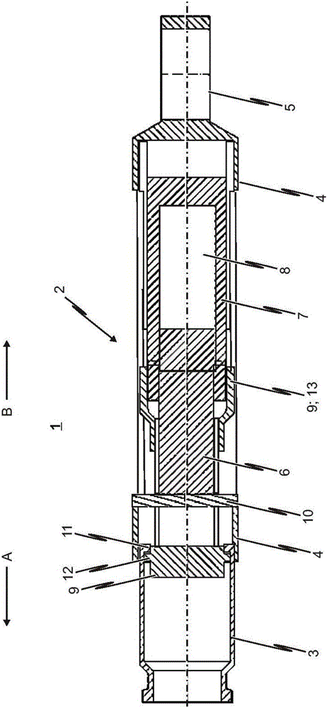
[0052] The structure of the damping mechanism 2 , which in this exemplary embodiment of the tension / impact damping device according to the invention is at least partially accommodated and formed in the ...

Example

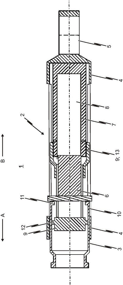
[0068] with in figure 1 The same as the first embodiment shown in, for example in Image 6 The exemplary second embodiment of the tensile force / impact damping device 1 according to the invention shown in also essentially has the following components:

[0069] - bumper housing 4, which is connected or connectable to the cabin of the vehicle;

[0070] - a force-transmitting element 3 for transmitting a tensile or compressive force to the damper housing 4 when required, said force-transmitting element 3 being movable relative to the damper housing 4 both in the direction of tension A and in the direction of impact B; as well as

[0071] - a damping mechanism 2 which is at least partially accommodated and formed in the damper housing 4 and which dampens the movement of the force transmission element relative to the damper housing 4 during the transmission of tensile / impact forces.

[0072] The damping mechanism 2 of the tensile force / impact damping device 1 according to the inv...

Example

[0075] The remainder of the exemplary second embodiment of the tensile force / impact damping device 1 according to the invention substantially corresponds to the reference in terms of structure and function Figure 1 to Figure 4 Illustrated first embodiment.

[0076] The invention is not limited only to the exemplary embodiment of the tensile force / impact damping device 1 according to the invention shown in the figures, but results from the generality of the features disclosed therein.


PUM


Abstract

The invention relates to a traction/impact device (1), in particular for medium buffer couplings of track-guided vehicles, in particular rail vehicles. The traction/impact device (1) comprises a damper housing (4), which is connected or connectable to a car body of the vehicle, and a force transmission element (3) for transferring tensile or impact forces onto the damper housing (4) Force transmission element (3) is movable relative to the damper housing (4) both in the pulling direction (A) and in the pushing direction (B). Furthermore, a damping mechanism (2) is provided, which is at least partially accommodated in the damper housing (4) and is designed to dampen the movement of the force transmission element relative to the damper housing (4) during traction/impact force transmission.

Description

technical field [0001] The invention relates to a tension / impact damping device, in particular a tension / impact damping device for a central damping coupler of a rail-mounted vehicle, in particular a rail vehicle. Background technique [0002] In particular, tension / impact damping arrangements for central damping couplers of rail vehicles are known from railway technology. Such a tension / impact device is used to absorb tension and compression forces during load switching, in particular in the pulling or pushing operation of long rail trains. This pull and impact dampener has been used for a long time. [0003] For example, document DE 363 03 60 A1 discloses a tension / impact damper in which two friction springs are arranged tensioned relative to one another in a force balance. One of the two friction springs is designed for tension and the other friction spring is designed for compression. A friction spring under tension relaxes in the direction of pressure when pressure o...

Claims


Application Information

Patent Timeline
IPC IPC(8): B61G9/08
CPCB61G9/08B61G11/12F16F9/16
Inventor K·U·科尔斯霍恩A·史泰恩卡姆普夫E·克瑙斯
Owner VOITH PATENT GMBH
Why Eureka
Try Eureka