
Power wire pay-off device

A technology of power wires and pay-off devices, which is applied in the field of electric power, can solve the problems of poor balance, unsmooth pay-off rotation, and easy front and rear movement of wheels, etc., and achieves strong adjustability, labor-saving push, and light rotation. Effect

Active Publication Date: 2017-04-19
江苏亚龙特种钢丝有限公司
View PDF11 Cites 1 Cited by
  • Summary
  • Abstract
  • Description
  • Claims
  • Application Information

AI Technical Summary

Problems solved by technology

[0003] In view of the above situation, in order to overcome the defects of the prior art, the present invention provides a power wire pay-off device, which effectively solves the difficulty of installing the pay-off reel on the frame of the existing pay-off device, and it is not easy to rotate when the pay-off is rotated. Smooth, the rack is not well balanced on the wheels, and the wheels are easy to move back and forth during the process of unwinding

Method used


Image

  • Power wire pay-off device
  • Power wire pay-off device
  • Power wire pay-off device

Examples


Embodiment Construction

[0016] The specific implementation manners of the present invention will be described in further detail below in conjunction with the accompanying drawings.

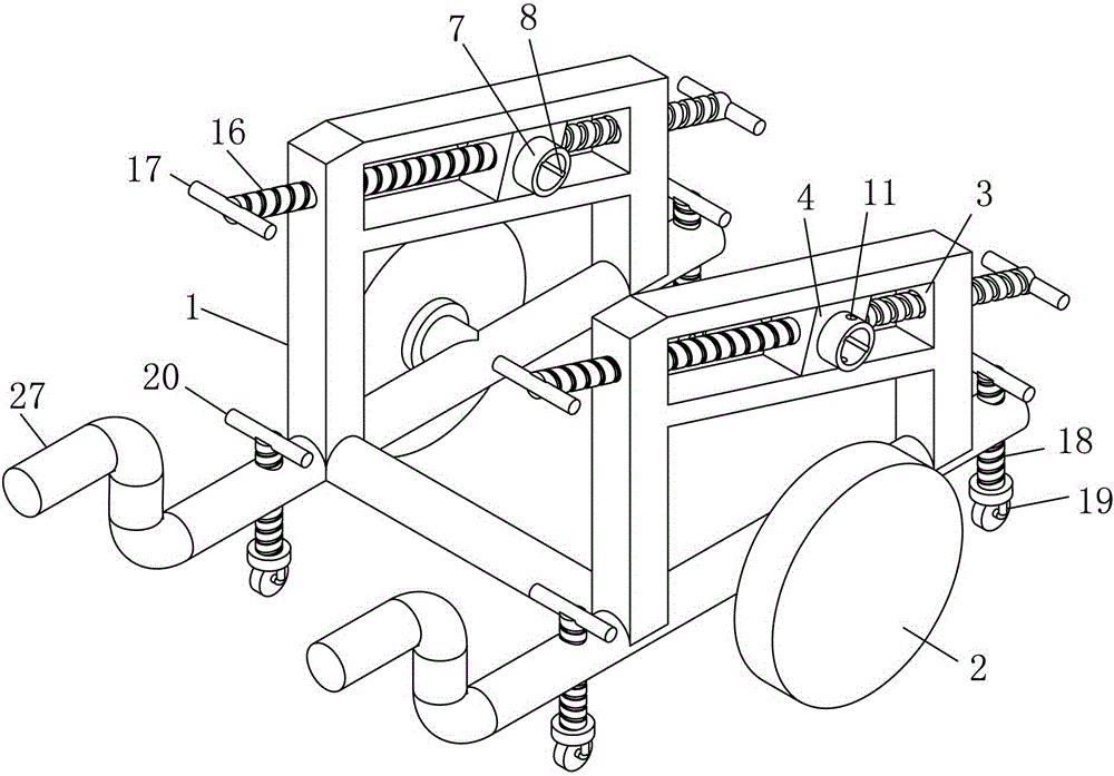
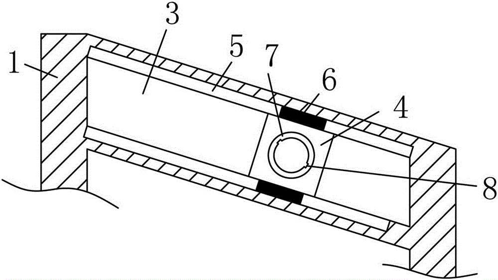
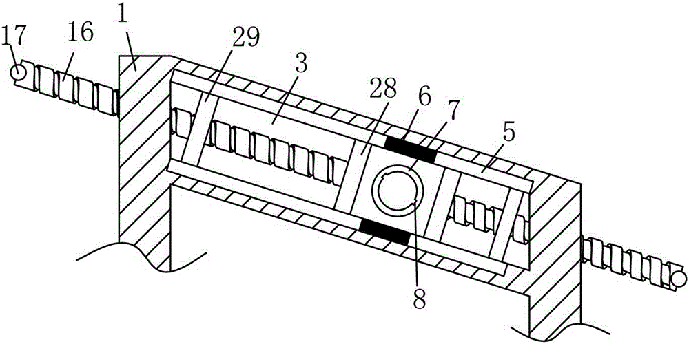
[0017] Depend on Figure 1 to Figure 8 Provide, the technical scheme of the present invention is, comprise frame 1, described frame 1 is provided with wheel 2 respectively, the left side of described frame 1 is provided with push armrest 27, and above described wheel 2 The front and rear sides of the rack 1 are respectively provided with corresponding chute 3, and the chute 3 is high on the left and low on the right, and is in an inclined shape with closed left and right ends and open front and rear, and a bearing seat 4 is slid inside the chute 3 , the upper end and the lower end of the chute 3 are respectively provided with a slideway 5 extending along the chute 3, and the upper and lower ends of the bearing seat 4 are respectively provided with a slider 6 extending into the slideway 5, and the bearing seat 4 4. A fix...


PUM


Abstract

The invention provides an electric wire pay-off device. The electric wire pay-off device solves the problems that it is difficult to install a pay-off disc of an existing pay-off device on a machine frame, pay-off rotation is not smooth, the machine frame cannot be well kept balanced on wheels and the wheels are likely to move forwards and backwards in the pay-off process. According to the technical scheme, the wheels are arranged at the front side end and the rear side end of the machine frame correspondingly; corresponding slide grooves are formed in the front side and the rear side of the portion, above the wheels, of the machine frame correspondingly; the left portions of the slide grooves are high, and the right portions of the slide grooves are low; the two ends of each slide groove are closed; each slide groove is in a front-back opened inclined shape; bearing pedestals are arranged in the slide grooves in a sliding manner; slide ways extending along the slide grooves are formed in the upper end and the lower end of each slide groove correspondingly; the upper ends and the lower ends of the bearing pedestals are each provided with a slide block extending into the corresponding slide way; fixed barrels are rotationally fixed in the bearing pedestals; axial through clamping grooves are formed in the inner circumferential faces of the fixed barrels; a supporting shaft is arranged between the two fixed barrels in a penetrating manner; clamping strips arranged in clamping grooves in a clamping manner are arranged on the supporting shaft; the portions, outside the machine frame, of the fixed barrels are each provided with a pin hole penetrating the corresponding fixed barrels and the supporting shaft; and pins are arranged in the pin holes in a penetrating manner.

Description

technical field [0001] The invention relates to the field of electric power, in particular to a power wire pay-off device. Background technique [0002] The existing power wire pay-off device is to place the shelf on two wheels, and then the shelf is provided with a shaft installation slot. Usually, the worker passes the shaft through the wire tray, and then puts the shaft on the shelf while lifting the two ends of the shaft. However, when people lift it up, because sometimes the power wire plate is relatively heavy, it takes many people to lift it up, which is time-consuming and laborious. After placing the shaft in the installation slot, the shaft is directly placed on the installation slot. , during the rotation process, due to the pressure of the wire reel, the friction between the shaft and the installation groove is large, and the rotation is not smooth when the wire is unwound, and it is easy to shake during the rotation process, and because two wheels are used to sup...

Claims


Application Information

Patent Timeline
Patent Type & Authority Patents(China)
IPC IPC(8): B65H49/36B65H49/32
CPCB65H49/324B65H49/36B65H2701/34
Inventor 杜旭凯曹真袁文飞颜凯宋亚东田新宇
Owner 江苏亚龙特种钢丝有限公司
Learn More